PWM driving method for displaying and driving LED

A driving method and display driving technology, which can be applied to static indicators, instruments, etc., can solve the problems of beating, occupying a lot of communication bandwidth and circuit resources, and achieve the requirements of reducing the communication rate and the effect of smooth brightness adjustment.

Inactive Publication Date: 2010-05-12
SHENZHEN TITAN MICRO ELECTRONICS
View PDF0 Cites 21 Cited by
  • Summary
  • Abstract
  • Description
  • Claims
  • Application Information

AI Technical Summary

Problems solved by technology

[0003] The present invention provides a PWM driving method for LED display driving to solve the problems existing in the existing LED driving control technology, such as jumping phenomenon during brightness adjustment, occupying more communication bandwidth and circuit resources

Method used


Image

  • PWM driving method for displaying and driving LED
  • PWM driving method for displaying and driving LED
  • PWM driving method for displaying and driving LED

Examples


specific Embodiment approach 1

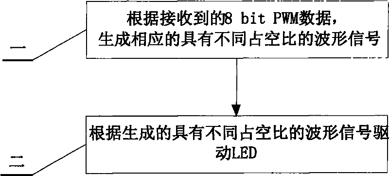
[0011] Specific implementation mode one: as Figure 1-7 As shown, this embodiment is made up of the following steps:

[0012] Step 1, according to the received 8-bit PWM data, generate corresponding waveform signals with different duty ratios through variable step length pulse width modulation;

[0013] Step 2, drive the LED according to the generated waveform signals with different duty ratios.

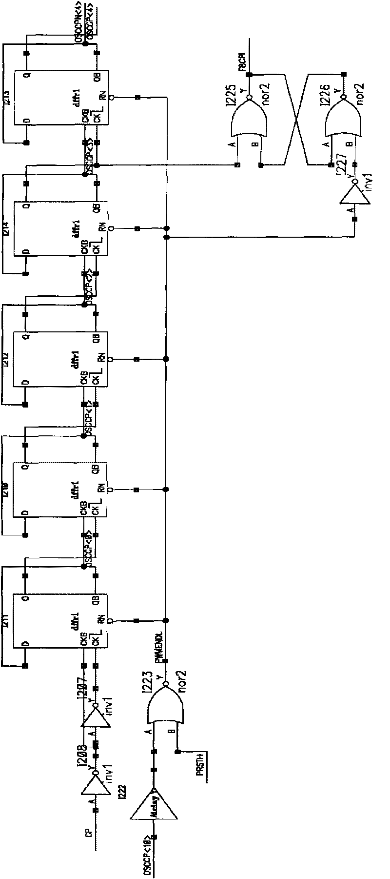
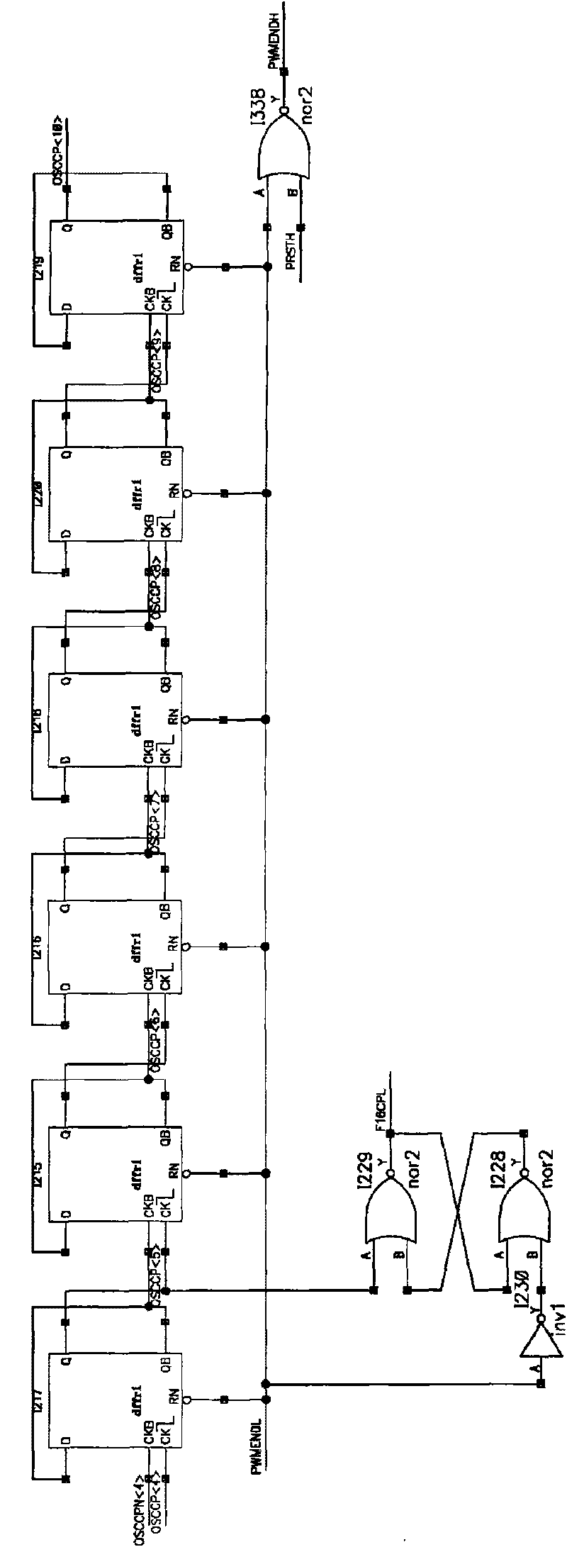
[0014] In this specific embodiment, the driving control of the LED may include two steps. First, through the variable step length pulse width modulation clock PWMCP generation circuit, according to the received 8-bit PWM data, generate corresponding signals with different duty ratios. Waveform signal. Input 8-bit data and output enhanced PWM code table as follows:

[0015] PWM control

OUTX output duty cycle

change step size

00H

0

01H

1 / 2048

1 / 2048

02H

3 / 2048

2 / 2048

03H

5 / 2048

2 / 2048

04H...


PUM


Abstract

The invention discloses a PWM driving method for displaying and driving an LED, which belongs to the field of LED driving control and solves the problems of jumping phenomenon, communication bandwidth occupation and more circuit resources during brightness adjustment in the conventional LED driving control technology. The PWM driving method comprises the following steps: generating corresponding waveform signals with different duty ratios according to received 8-bit PWM data; and driving the LED according to the generated waveform signals with the different duty ratios. The method for directly driving the LED for PWM control waveform through the generated waveform signals with variable duty ratio implements smoother brightness adjustment for the LED through fewer control bits, and greatly reduces the requirement on the communication rate.

Description

technical field [0001] The invention relates to a PWM driving method for LED display driving, which belongs to the field of LED driving control. Background technique [0002] In the current outdoor / indoor LED driving IC display data driving method, PWM (Pulse Width Modulation) technology is commonly used to control the brightness or grayscale of the LED, and the driving IC that realizes the driving scheme adopted by this technology generally adopts 2 to the nth power series to complete, the increased pulse width of each level is fixed at 1 / 2 n . In practical applications, since the LED lamp chip is a current-mode device, the performance of the duty cycle and the luminous brightness is nonlinear, that is, when the PWM width increases linearly, the luminous brightness of the LED is nonlinear. Especially for the previous series, in the project where the duty cycle gradually increases, the brightness of each level changes very obviously when the duty cycle is small, and the LE...

Claims


Application Information

Patent Timeline
Patent Type & Authority Applications(China)
IPC IPC(8): G09G3/14G09G3/32
Inventor 门洪达张伟冯根强权进国田道璟
Owner SHENZHEN TITAN MICRO ELECTRONICS
Why Eureka
Try Eureka