Load alleviation assembly for a window, door or similar

A technology of unloading device and spring device, which is applied to the suspension device of wing leaf, door/window accessories, control mechanism of wing leaf, etc., can solve the problems of users not getting it.

Active Publication Date: 2013-11-13
ROTO FRANK AG
View PDF6 Cites 0 Cited by
  • Summary
  • Abstract
  • Description
  • Claims
  • Application Information

AI Technical Summary

Problems solved by technology

But in this device, the user does not get any information about whether the correct bias voltage has been generated

Method used


Image

  • Load alleviation assembly for a window, door or similar
  • Load alleviation assembly for a window, door or similar
  • Load alleviation assembly for a window, door or similar

Examples


Embodiment Construction

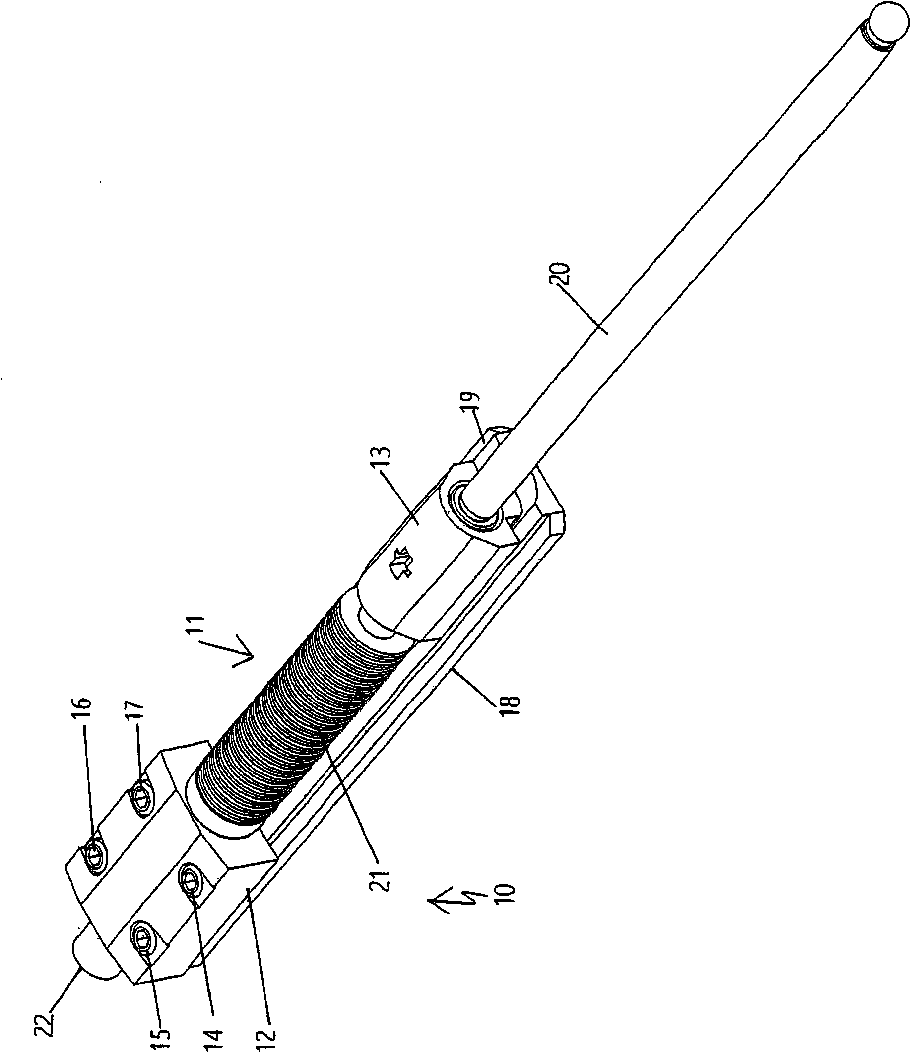
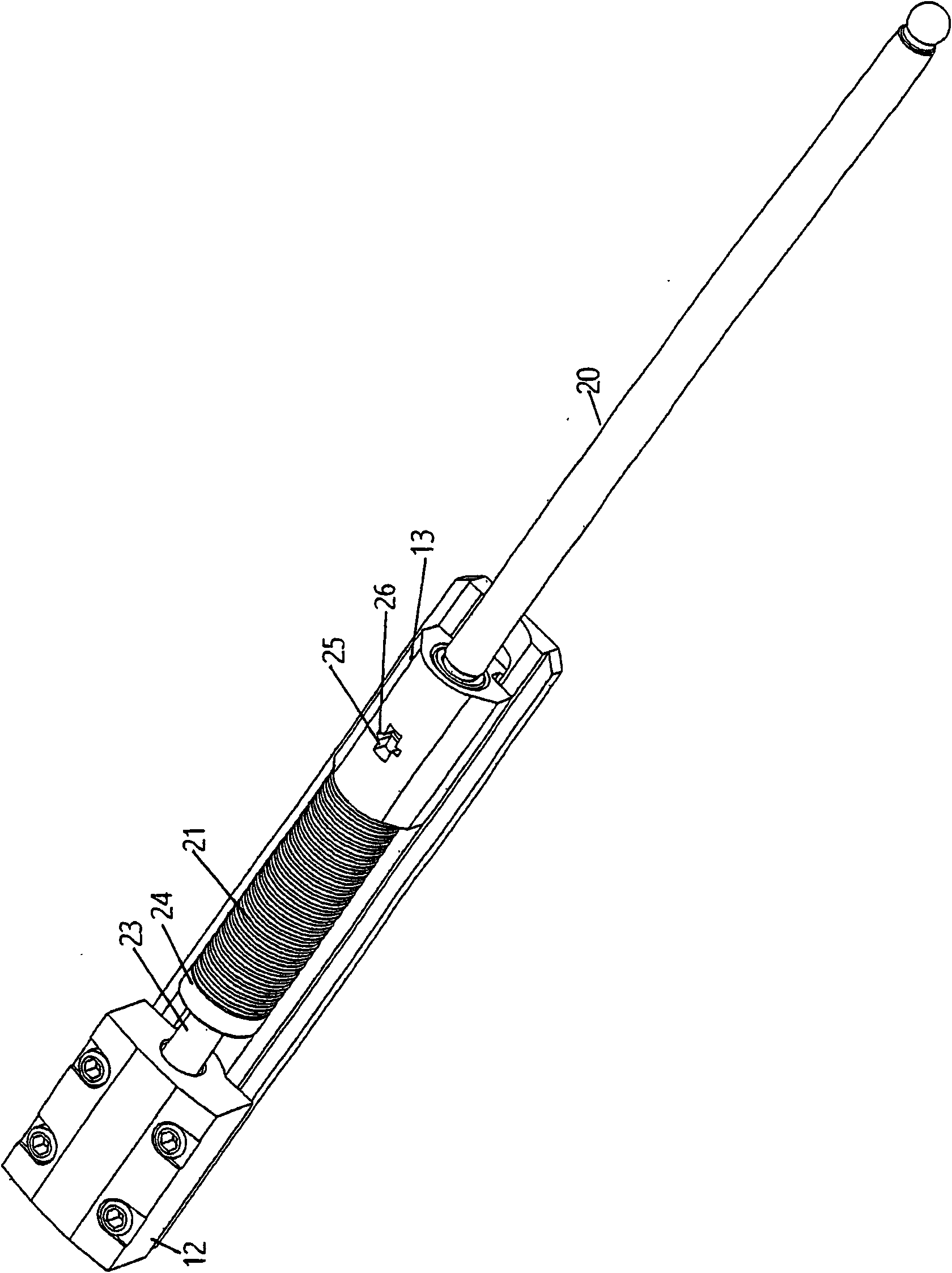
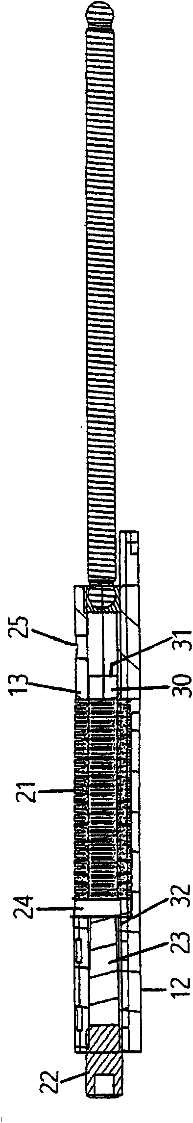
[0046] figure 1 The wing-side part of an unloading device 10 is shown, with a wing-side support 11 comprising a fixed support part 12 and a support part 13 movable relative to it. The fixedly arranged abutment part 12 can be fastened securely to a leaf in the exemplary embodiment shown by means of four piercing screws. In particular, the fixed support member 12 is designed to be mounted on an aluminum window. The groove flanges overhanging the guides 18 , 19 can be pushed apart by four screws 14 - 17 . This means that the fastening support part 12 can be inserted into the fitting groove of the aluminum window and can be fixed there. A spring device 21 is arranged between the movable support member 13 and the fixed support member 12, and it is figure 1 Medium is relaxing. The spring arrangement can be biased by adjusting the screw 22 . The spring device 21 is formed in this exemplary embodiment from a plurality of disc springs, but it can also be realized differently, for ...


PUM


Abstract

Unit (20) to take up the weight of a door or window, at a fixed frame, is between mountings (11) at the frame and the door / window panel. Each mounting has a fixed section (12) and a moving section (13), with a spring (21) between them. An optical or acoustic indicator shows the spring tension.

Description

technical field [0001] The invention relates to an unloading device, by means of which at least a part of the leaf load of a leaf of a window, door etc. can be transferred to a fixed frame, said unloading device comprising a frame-side and a leaf-side support and a load transfer element disposed between supports, at least one of which has a fixed support member and a movable support member movable relative to the fixed support member, and between said support members A spring device is provided. Background technique [0002] From EP1837472A1 known windows, doors, etc., which comprise a fixed frame and an openable and closable leaf, also comprise a leaf unloading device for introducing at least part of the leaf load into the fixed frame, the leaf unloading device having A frame-side and a leaf-side bearing means for supporting a load transfer mechanism and a spacing equalizer cooperating with the load transfer mechanism, which compensates for the bearing means occurring duri...

Claims


Application Information

Patent Timeline
Patent Type & Authority Patents(China)
IPC IPC(8): E05F7/06E05D15/52E05D11/00
CPCE05Y2201/702E05Y2600/20E05D15/5211E05Y2201/492E05F7/06E05Y2400/44E05Y2400/818E05Y2201/474E05F15/00E05D15/30E05Y2900/148E05F7/005
Inventor D·哈内尔M·西格勒
Owner ROTO FRANK AG
Why Eureka
Try Eureka