A low-voltage ride-through detection device for photovoltaic power generation compatible with dual voltage levels
A low-voltage ride-through and voltage level technology, applied in photovoltaic power generation, photovoltaic system monitoring, photovoltaic modules and other directions, can solve the problems of detection system voltage level, capacity, lack of measurement methods, etc., achieve small size, easy installation, good protection effect of action
- Summary
- Abstract
- Description
- Claims
- Application Information
AI Technical Summary
Problems solved by technology
Method used
Image

Examples
Embodiment 1
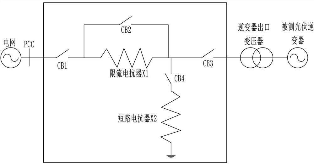
[0031] The voltage drop characteristics generated by the impedance divider voltage drop generator are closest to the voltage drop characteristics of the actual grid fault, and can accurately reflect the interaction and interaction between the grid and the photovoltaic inverter during the grid fault, so the impedance divider is used The way to design low voltage ride through detection device.
[0032] as attached figure 1 As shown, in the present invention, the controllable circuit breaker CB1, the current limiting reactor X1, the controllable circuit breaker CB3 and the inverter outlet transformer are connected in series in sequence, the controllable circuit breaker CB2 is connected in parallel with the current limiting reactor X1, and the current limiting reactor A short-circuit reactor X2 is connected to the line between X1 and the controllable circuit breaker CB3 through the controllable circuit breaker CB4. The invention is connected in series between the photovoltaic inv...
Embodiment 2
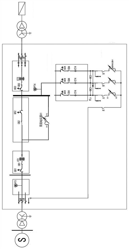
[0047] as attached figure 2 As shown, a voltage transformer PT1 is set on the line between the controllable circuit breaker CB1 and the power grid, a switch QS1 is set between the voltage transformer PT1 and the controllable circuit breaker CB1, and on the rear side of the controllable circuit breaker CB1 A current transformer CT1 is provided; a switch QS2 is arranged in series behind the controllable circuit breaker CB2, and the current-limiting reactor X1 shown is connected in parallel with the controllable circuit breaker CB2 and the switch QS2; at the front and rear sides of the controllable circuit breaker CB3 A switch QS3 and a current transformer CT3 are respectively connected in series;
[0048] A voltage transformer PT4 is arranged in series on the front side of the current transformer CT4. There are three current transformers CT4 and they are respectively located in three lines. A switch QS4 and a current transformer are respectively connected in series on both side...
PUM
 Abstract
Description
Claims
Application Information
 - R&D Engineer
- R&D Manager
- IP Professional
- Industry Leading Data Capabilities
- Powerful AI technology
- Patent DNA Extraction
Browse by: Latest US Patents, China's latest patents, Technical Efficacy Thesaurus, Application Domain, Technology Topic.
© 2024 PatSnap. All rights reserved.Legal|Privacy policy|Modern Slavery Act Transparency Statement|Sitemap