A dispensing valve driven by giant magnetostrictive rods
A technology of giant magnetostrictive rod and glue dispensing valve, which is applied to the device for coating liquid on the surface, coating and other directions, can solve the problems of difficult to realize the needle stroke, complicated manufacturing process, small driving force, etc., and achieve quantitative control. The effect of micro-spraying and avoiding the frequency doubling phenomenon
- Summary
- Abstract
- Description
- Claims
- Application Information
AI Technical Summary
Problems solved by technology
Method used
Image
Examples
Embodiment 1
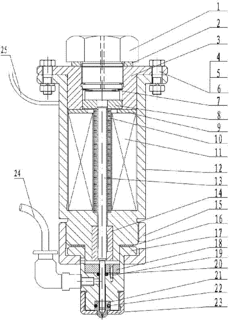
[0025] See attached figure 1 , the end cover 3 is fixed on the housing 12 through the bolt 4, the gasket 5, and the nut 6, and the excitation coil 11 is fixed in the housing 12 through the end cover 3 and the gasket 9; the cylindrical giant magnetostrictive rod 10 is placed In the center of the excitation coil 11, one end is tightly fixed on the concave platform of the housing 12, and the other end is supported by the magnetic guide sheet 8 against the spray needle 13 pressed by the disc spring 7, and the end cover 3 is provided with a spinning screw 1, Between the end cover 3 and the spinning screw 1, there is a preload adjusting gasket 2, and the spinning screw 1 tightens the disc spring 7; the lower end of the housing 12 is provided with a guide sleeve 14, which is used for guiding and centering the spray needle 13 , the nozzle 21 is fixed on the glue cavity 17 through the nozzle sleeve 23, and the first O-ring 22 is arranged between the nozzle 21 and the glue cavity 17 to ...
Embodiment 2
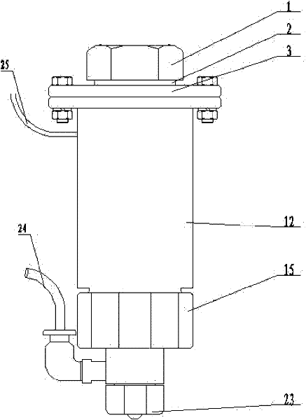
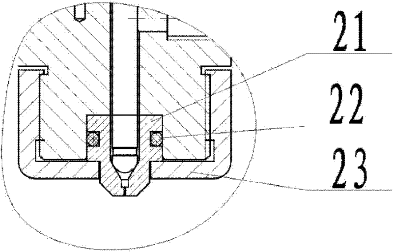
[0033] See attached Figure 4 , this example is a contact dispensing valve, attached Figure 5 It is the front view of the contact dispensing valve, attached Image 6 An enlarged view of the dispensing tip of the dispensing valve.
[0034] Its working principle: apply a PWM voltage to the excitation coil 11 through the power supply and the control circuit 25, such as Figure 10 When the excitation voltage is zero, the cylindrical giant magnetostrictive rod 10 is in the initial state without elongation, and it is subjected to the precompression stress generated by the disc spring 7. At this time, the spray needle 13 is at the bottom position, pressing against the nozzle 21 , to ensure that no glue flows out from the nozzle 21; when the excitation voltage is V on At this time, the excitation coil 11 generates a magnetic field, under the action of this magnetic field, the cylindrical giant magnetostrictive rod 10 is extended, and the injection needle 13 is driven to move upwar...
Embodiment 3
[0036] Participate in Figure 7 , the base 27 of this embodiment integrates the nozzle 21, the glue cavity 17 and the nozzle sleeve 23 in Embodiment 1 to reduce assembly errors and attach Figure 8 It is an enlarged view of the contact between the base 27 and the spray needle 13;
PUM
 Abstract
Description
Claims
Application Information
 - R&D
- Intellectual Property
- Life Sciences
- Materials
- Tech Scout
- Unparalleled Data Quality
- Higher Quality Content
- 60% Fewer Hallucinations
Browse by: Latest US Patents, China's latest patents, Technical Efficacy Thesaurus, Application Domain, Technology Topic, Popular Technical Reports.
© 2025 PatSnap. All rights reserved.Legal|Privacy policy|Modern Slavery Act Transparency Statement|Sitemap|About US| Contact US: help@patsnap.com


