Spot gluing valve based on giant magnetostrictive rod drive

A technology of giant magnetostrictive rod and glue dispensing valve, which is applied to devices and coatings that apply liquid to the surface, can solve the problems of difficulty in realizing the needle stroke, complicated manufacturing process, small driving force, etc., and achieve quantitative control. The effect of micro-spraying and avoiding the frequency doubling phenomenon

Inactive Publication Date: 2010-07-28
CENT SOUTH UNIV
View PDF4 Cites 3 Cited by
  • Summary
  • Abstract
  • Description
  • Claims
  • Application Information

AI Technical Summary

Problems solved by technology

The injection accuracy of the jet dispensing valve is directly related to the viscosity of the glue that can be injected and the stroke and acceleration of the injection needle in the injector. The smaller the stroke of the needle and the greater the acceleration, the higher the injection accuracy and the larger the injection. High-viscosity glue; however, the driving force of the pneumatically driven jet dispensing valve is small, the response time is slow (5-10ms), and it is difficult to achieve a small needle stroke, so it is difficult to achieve micro-volume and high-frequency glue injection; At the same time, because the needle directly collides with the base, the material and size of the needle are greatly limited and the service life is relatively short, and the coaxiality with the cylinder is required to be high, so the manufacturing process is complicated

Method used


Image

  • Spot gluing valve based on giant magnetostrictive rod drive
  • Spot gluing valve based on giant magnetostrictive rod drive
  • Spot gluing valve based on giant magnetostrictive rod drive

Examples


Embodiment 1

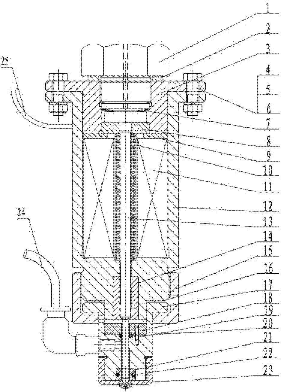
[0025] See attached figure 1 , the end cover 3 is fixed on the housing 12 through the bolt 4, the gasket 5, and the nut 6, and the excitation coil 11 is fixed in the housing 12 through the end cover 3 and the gasket 9; the cylindrical giant magnetostrictive rod 10 is placed In the center of the excitation coil 11, one end is tightly fixed on the concave platform of the housing 12, and the other end is supported by the magnetic guide sheet 8 against the spray needle 13 pressed by the disc spring 7, and the end cover 3 is provided with a spinning screw 1, Between the end cover 3 and the spinning screw 1, there is a preload adjusting gasket 2, and the spinning screw 1 tightens the disc spring 7; the lower end of the housing 12 is provided with a guide sleeve 14, which is used for guiding and centering the spray needle 13 , the nozzle 21 is fixed on the glue cavity 17 through the nozzle sleeve 23, and the first O-ring 22 is arranged between the nozzle 21 and the glue cavity 17 to ...

Embodiment 2

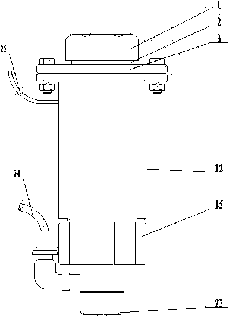
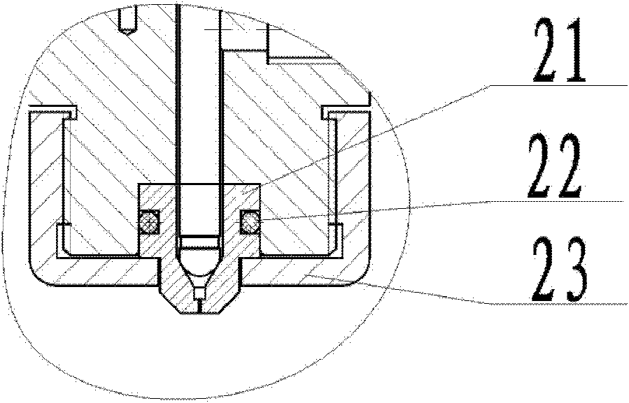
[0033] See attached Figure 4 , this example is a contact dispensing valve, attached Figure 5 It is the front view of the contact dispensing valve, attached Figure 6 An enlarged view of the dispensing tip of the dispensing valve.

[0034] Its working principle: apply a PWM voltage to the excitation coil 11 through the power supply and the control circuit 25, such as Figure 10 When the excitation voltage is zero, the cylindrical giant magnetostrictive rod 10 is in the initial state without elongation, and it is subjected to the precompression stress generated by the disc spring 7. At this time, the spray needle 13 is at the bottom position, pressing against the nozzle 21 , to ensure that no glue flows out from the nozzle 21; when the excitation voltage is V on At this time, the excitation coil 11 generates a magnetic field, under the action of this magnetic field, the cylindrical giant magnetostrictive rod 10 is elongated, and the injection needle 13 is driven to move upw...

Embodiment 3

[0036] Participate in Figure 7 , the base 27 of this embodiment integrates the nozzle 21, the glue cavity 17 and the nozzle sleeve 23 in Embodiment 1 to reduce assembly errors and attach Figure 8 It is an enlarged view of the contact between the base 27 and the spray needle 13;


PUM


Abstract

The invention discloses a spot gluing valve based on giant magnetostrictive rod drive, which comprises a spray needle (13) and a valve body. An end cover (3) is fixed on a shell (12), and an excitation coil (11) is fixed in the shell (12) through the end cover (3); an elastic pre-tightening device is arranged on the end cover (3); the upper end of the spray needle (13) is tightly pressed by the elastic pre-tightening device, and the lower end of the spray needle (13) enters the valve body through the shell (12); a giant magnetostrictive rod is arranged at the center of the excitation coil (11); one end of the giant magnetostrictive rod is tightly butted and fixed on the shell (12), and the other end of the giant magnetostrictive rod is butted on the spray needle (13) which is tightly pressed by the elastic pre-tightening device through a magnetic conduction sheet (8); the end cover (3), the magnetic conduction sheet (8) and the shell (12) are magnetic conduction materials; and the end cover (3), the magnetic conduction sheet (8), the shell (12) and the giant magnetostrictive rod form a closed magnetic circuit. In the invention, the spot gluing valve based on giant magnetostrictive rod drive has the advantages of simple structure, convenient use, high spraying frequency, high spraying accuracy and long service life.

Description

technical field [0001] The invention discloses a non-contact and contact dual-purpose dispensing device, in particular to a giant magnetostrictive drive dispensing valve, which relates to the technical field of microelectronic equipment, and is mainly suitable for encapsulation of microelectronic and optoelectronic chips . Background technique [0002] In the existing technical field, the glue spraying equipment used for microelectronic packaging is mainly based on the pneumatic glue spraying equipment of Asymtek Company. It controls the high-pressure air flow in and out through the air control valve to push the driver piston to move up and down, thereby pushing the injection needle to reciprocate, and realizes the injection process of extruding glue. The injection accuracy of the jet dispensing valve is directly related to the viscosity of the glue that can be injected and the stroke and acceleration of the injection needle in the injector. The smaller the stroke of the ne...

Claims


Application Information

Patent Timeline
Patent Type & Authority Applications(China)
IPC IPC(8): B05C5/00B05C11/10
Inventor 段吉安邓圭玲葛志旗彭志勇谢敬华
Owner CENT SOUTH UNIV
Why Eureka
Try Eureka