Automatic assembly method for press key support frames

A technology of automatic assembly and support frame, applied in the direction of electrical components, electric switches, circuits, etc., can solve problems such as consuming a lot of time

Inactive Publication Date: 2010-08-04
SOLID YEAR
View PDF0 Cites 7 Cited by
  • Summary
  • Abstract
  • Description
  • Claims
  • Application Information

AI Technical Summary

Problems solved by technology

[0002] The insertion method of the general button support frame is mostly based on manpower, and the button support frame is installed and arranged in the bottom plate one by one according to the key position manually, and then pressed down with a pressing plate to fo

Method used


Image

  • Automatic assembly method for press key support frames
  • Automatic assembly method for press key support frames
  • Automatic assembly method for press key support frames

Examples


no. 1 example

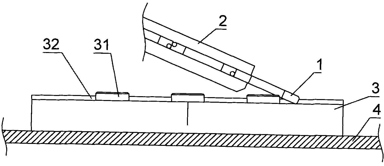
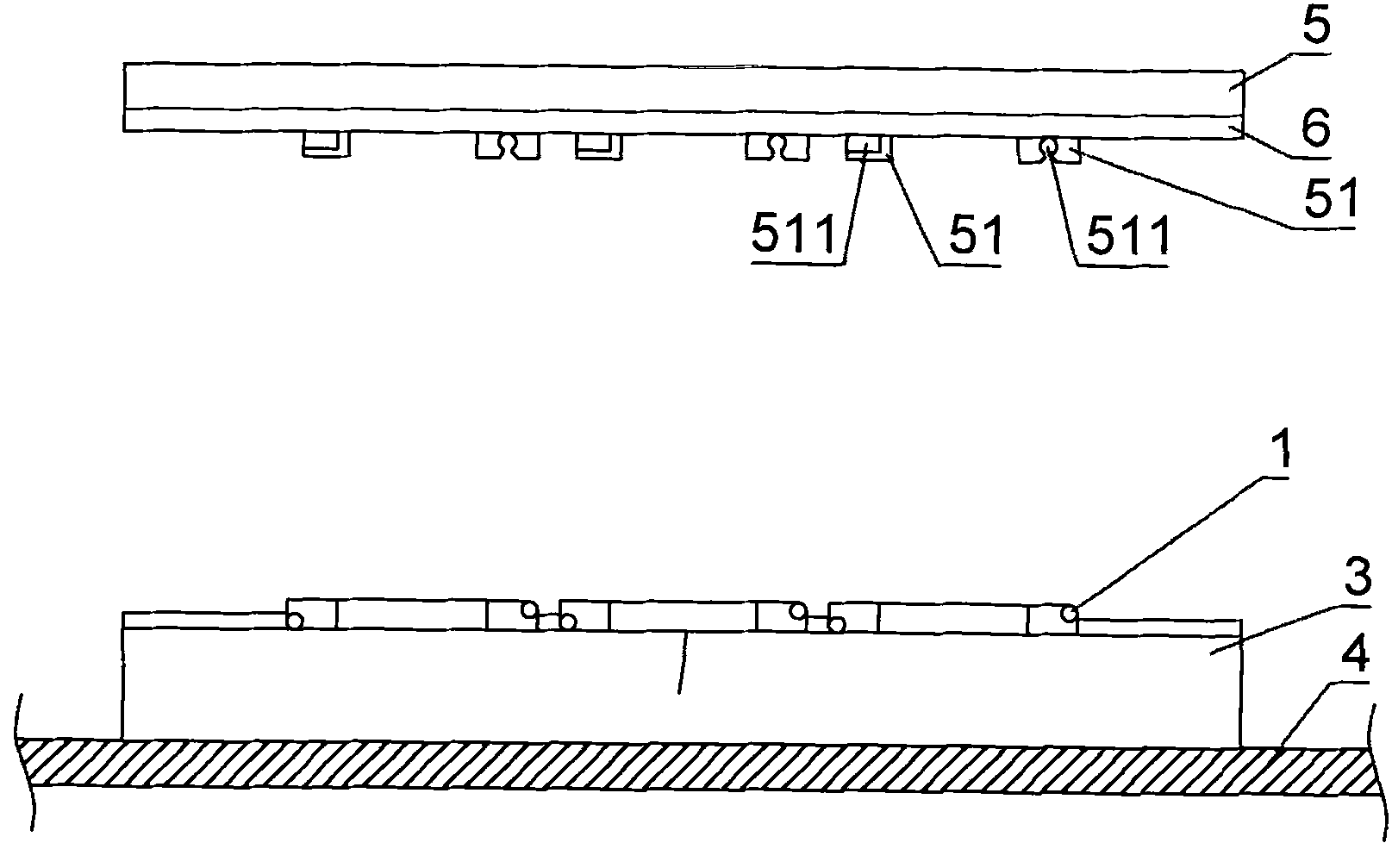
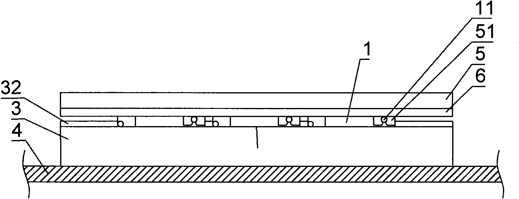
[0025] see figure 1 , figure 2 , image 3 , Figure 4 , Figure 5 According to the first embodiment of the present invention, an automatic assembly method for a key support frame includes: a key support frame 1 , a track 2 , a clamp 3 , a conveyor belt 4 , a bottom plate 5 , and a flexible circuit board 6 .

[0026] A protruding shaft 11 and a round hole 12 are provided on both sides of the front end of the key support frame 1. The key support frame 1 is arranged according to the required direction and passes through a track 2, and the front end of the key support frame 1 slides down onto the fixture 3. The fixture 3 is placed on a conveyer belt 4, and its clamp 3 is provided with a protruding part 31 and a positioning part 32, and its protruding part 31 can take the sliding button support frame 1 away from the track 2, and position it on the positioning part 32. The fixture 3 is moved to the lower side of a base plate 5, the flexible circuit board 6 and a connecting seat...

no. 2 example

[0029] In this embodiment, the same components as those in the first embodiment are marked with the same symbols.

[0030] see Figure 6 , The automatic assembly method of a button support frame in this embodiment includes a button support frame 1, a track 2, a clamp 3, a conveyor belt 4, a bottom plate 5, a flexible circuit board 6, and an elastic body 7.

[0031] An elastic body 7 is arranged below the protruding part 31 of the clamp 3. When the base plate 5 moves downward, the base plate 5 will press the protruding part 31 to move down to allow the base plate 5 to move to an appropriate position. When the base plate 5 is taken out, its protruding The extension part 31 will return to its original position.

[0032] The configurations and functions of other components of this embodiment are the same as those of the first embodiment, so details will not be repeated here.

no. 3 example

[0034] In this embodiment, the same components as those in the first embodiment are marked with the same symbols.

[0035] see Figure 7 , The automatic assembly method of a button support frame in this embodiment includes a button support frame 1, a track 2, a clamp 3, a conveyor belt 4, a bottom plate 5, a flexible circuit board 6, and a bump 8.

[0036] A bump 8 is arranged above the track 4, and when the protruding part 31 takes the sliding button support frame 1 away from the track 2, the bump 8 passes above the button support frame 1 to prevent the button support frame 1 from jumping off.

[0037] The configurations and functions of other components of this embodiment are the same as those of the first embodiment, so details will not be repeated here.


PUM


Abstract

The invention relates to an automatic assembly method for press key support frames. The automatic assembly method is characterized in that the press key support frames are arrayed according to the required direction and slide through a guide rail to fall on a clamp sequentially; the clamp is arranged on a conveyer belt; the clamp is provided with a convex extension part; the convex extension part can lead the press key support frames sliding down away from the guide rail, position the press key on the clamp and move the clamp below a bottom plate; a flexible circuit board and a connecting seat which is combined with the press key support frames are arranged below the bottom plate; and when being pressed down, the press key support frame is forced to be clamped into the connecting seat of the press key support frame. The invention provides the efficiently automatic assembly method.

Description

technical field [0001] The invention relates to a method for assembling a button support frame, especially refers to that the button support frame is arranged according to the required direction, slides down from a guide rail to a fixture or a bottom plate in sequence, and the protruding part of the fixture or the bottom plate is used The inverted L-shaped hook takes it away, and then presses down from the bottom plate and the pressure plate respectively to provide the bottom plate containing the key support frame. Background technique [0002] The insertion method of the general button support frame is mostly based on manpower, and the button support frame is installed and arranged in the bottom plate one by one according to the key position manually, and then pressed down with a pressing plate to force it to be embedded. The card is positioned on the bottom plate. However, it takes a lot of time and manpower to complete the installation of several keys on a keyboard surfac...

Claims


Application Information

Patent Timeline
IPC IPC(8): H01H13/88
Inventor 梁徽湖
Owner SOLID YEAR
Why Eureka
Try Eureka