Locking type decorative plate

A technology of decorative panels and locks, which can be applied to floors, buildings, building structures, etc., and can solve problems such as lack of heat to adjust indoor temperature, floor cannot be routed, and single function.

Inactive Publication Date: 2010-08-11
李新发
View PDF6 Cites 5 Cited by
  • Summary
  • Abstract
  • Description
  • Claims
  • Application Information

AI Technical Summary

Problems solved by technology

Its shortcomings are: 1. It has a single function, and it cannot be routed in the floor; 2. It does not have the function of heating and adjusting the indoor temperature

Method used


Image

  • Locking type decorative plate
  • Locking type decorative plate
  • Locking type decorative plate

Examples


Embodiment 1

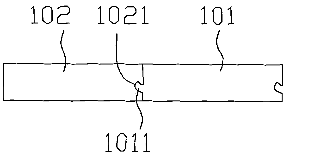
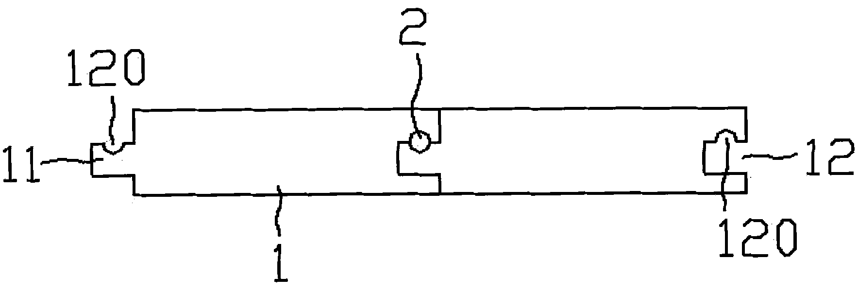
[0029] Example 1, see figure 2 , The lock type decorative board includes a plate 1 and a plug-in body 2. The board 1 is formed with a tenon 11 and a groove 12, the tenon 11 is inserted into the groove 12, and at least one plug-in body 2 is inserted into the sleeve In the matching recess 120 on the tenon 11 and the groove 12.

[0030] The plug-in body 2 is a metal body or a non-metal body made of hard materials.

[0031] The plug-in body 2 is round, square, elliptical, triangular or other irregular shapes.

[0032] In this way, the self-locking between the two plates can be realized.

Embodiment 2

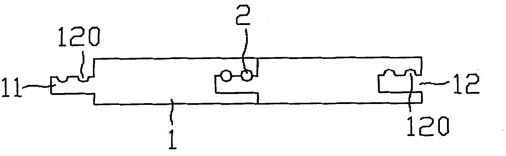
[0033] Example 2, see image 3 There are two plug-in bodies 2, one plug-in body is made of hard material, and the other plug-in body is a network cable, a telephone line or a wire. The rest is the same as in Example 1.

Embodiment 3

[0034] Example 3, see Figure 4 , The tenon 11 and the groove 12 have a curved surface, and the rest are the same as in embodiment 1.


PUM


Abstract

The invention relates to a locking type decorative plate, which comprises a plate block and inserting bodies, wherein a tenon and a groove are molded on the plate block, the tenon is inserted into the groove, and at least one inserting body is inserted and sleeved in a matched notch on the tenon and the groove. The locking type decorative plate realizes the self-locking purpose and simultaneously has the functions of running wires and regulating indoor temperature.

Description

Technical field: [0001] The invention relates to the technical field of decorative panels, in particular to a heating decorative panel. Background technique: [0002] There are many lock structures for wooden floors, such as figure 1 As shown, there is a wooden floor that uses a plug 1011 and a groove 1021 to connect two wooden blocks 101 and 102 together. It has a simple structure and convenient connection, which makes the installation of the wooden floor very simple. Its shortcomings are: 1. It has a single function and cannot be routed in the floor; 2. It does not have the function of heating to adjust the indoor temperature. Summary of the invention [0003] The technical problem to be solved by the present invention is to provide a lock type decorative board, which not only realizes self-locking but also has the functions of wiring and adjusting indoor temperature. [0004] To solve the above technical problems, the present invention adopts the following technical solutions: ...

Claims


Application Information

Patent Timeline
Patent Type & Authority Applications(China)
IPC IPC(8): E04F15/02E04F15/06
Inventor 李新发
Owner 李新发
Why Eureka
Try Eureka