Collection cabinet

A collection and cabinet technology, applied in the field of collection cabinets, can solve the problems of unstable placement, damaged collections, time-consuming and laborious, etc., and achieve the effects of compact overall structure of the cabinet, labor-saving and convenient storage, and reduced damage.

Active Publication Date: 2010-08-18
NINGBO BANGDA INDAL
View PDF8 Cites 3 Cited by
  • Summary
  • Abstract
  • Description
  • Claims
  • Application Information

AI Technical Summary

Problems solved by technology

[0004] Although the above-mentioned two patents disclose two kinds of storage cabinet structures with different structures, the storage cabinets in the above-mentioned patents are all provided with drawers, which are only suitable for storing documents or small collections. As for the collections in the collection, due to their large volume and irregular shape, they cannot be stored in drawers, and a large collection cabinet is required for collection; considering the needs of display, the collections placed in the cabinet should be taken out and put away frequently. However, the bottom plate of the general cabinet is a fixed structure and cannot be flexibly expanded and moved. Therefore, it is more troublesome to take out the collection or put it into the cabinet, which is not only time-consuming and laborious, but also easily damaged due to unstable placement.

Method used


Image

  • Collection cabinet
  • Collection cabinet
  • Collection cabinet

Examples


Embodiment 2

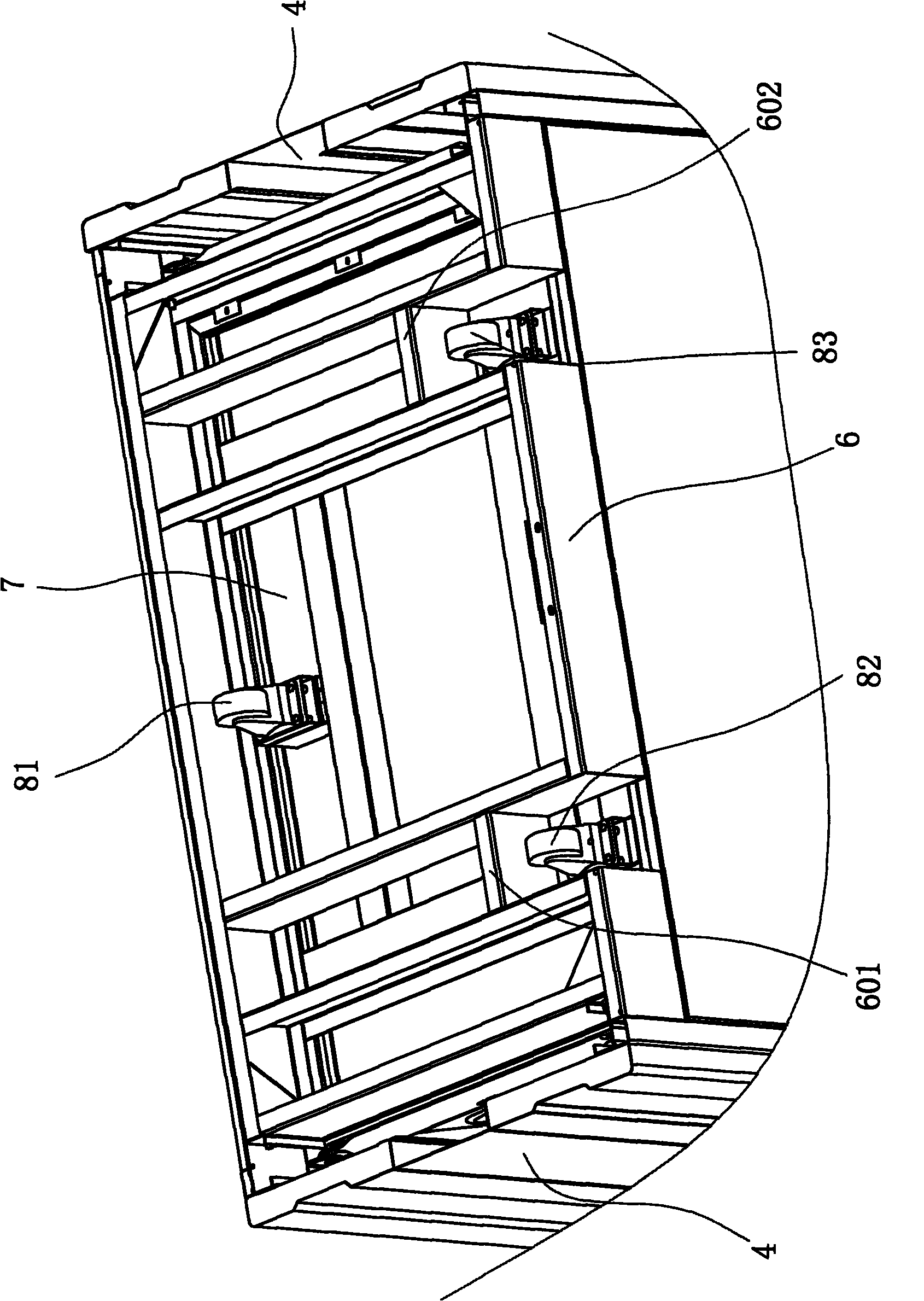
[0034] In the second embodiment, there are still three first rollers 81, second rollers 82 and third rollers 83 arranged in a triangular distribution at the bottom of the drawing plate, the difference is the specific position distribution of the rollers, wherein the bottom of the drawing plate 7 is A first roller 81 and a second roller 82 are provided on the side close to the backboard, and a third roller 83 is provided on the bottom of the drawing plate 7 on the side close to the cabinet door. Then, correspondingly, the chassis 6 is welded by four beams 61, a main beam 62 and two crosspieces 63 to form two chambers 691, a chamber 692 and a chamber 693, wherein, on the chamber 693, the same A limit baffle 60 is provided to limit the linear sliding position of the roller. When the drawer 7 was pulled out of the cabinet completely, the first roller 81 and the crosspiece 63 in the chamber 691 were against each other, and the second roller 82 was against the crosspiece 63 in the c...


PUM


Abstract

The invention relates to a collection cabinet comprising a body. The body of the collection cabinet is provided with a top plate, a back plate, side plates and a base, and the front side of the body of the collection cabinet is provided with a door. The collection cabinet is characterized in that the base comprises a chassis and a pull plate, the chassis is fixedly connected to the body of the collection cabinet, the pull plate can move back and force relatively to the chassis, the bottom surface of the pull plate is butted on the upper surface of the chassis, the bottom of the pull plate is provided with rolling wheels, the chassis is provided with cavity which can hold the rolling wheels and facilitate the linear slide of the rolling wheels, and two sides of the pull plate, which correspond to the side plates, are in fit connection with the body of the collection cabinet through rolling guideways. Compared with the prior art, the collection cabinet has the advantages that because the base is in the movable structure, and the pull plate can move relatively to the chassis, the collection can be stored more conveniently with least labor, and because the rolling wheels arranged at the bottom of the pull plate can be rightly and totally embedded in the cavity of the chassis to form embedded rolling wheel structures, the collection cabinet hereby has more compact and attractive structure.

Description

technical field [0001] The invention relates to a device used for museum collections, in particular to a collection cabinet for storing irregular and special-shaped collection items. Background technique [0002] The various collections in the museum include animal specimens, fossils, various cultural relics and cultural relics, calligraphy and paintings, etc. In order to ensure that these precious cultural relics and collections are not damaged and worn, special storage equipment is required to store different collections. [0003] Among the storage cabinets that have been disclosed in the prior art, the Chinese utility model patent "Museum Storage Cabinet" with the patent number ZL200820126160.0 discloses a storage cabinet with such a structure, including a cabinet body and a cabinet door positioned on the front of the cabinet body. It is characterized in that several drawers are arranged in the cabinet, and spaces are arranged above the several drawers. Another example i...

Claims


Application Information

Patent Timeline
IPC IPC(8): A47B53/00A47B57/00
Inventor 朱建华
Owner NINGBO BANGDA INDAL
Why Eureka
Try Eureka