Enhanced prism sheet

A technology of prism film and truncated cone, which is applied in the direction of light guide, optics, instruments, etc., can solve the problems of not getting better effect, poor light guiding effect, and decrease of prism film brightness, so as to avoid light interference, expand viewing angle, and good focus light effect

Active Publication Date: 2013-07-24
BOE TECH GRP CO LTD +1
View PDF0 Cites 0 Cited by
  • Summary
  • Abstract
  • Description
  • Claims
  • Application Information

AI Technical Summary

Problems solved by technology

This is because in the axial direction of the elongated prism, the prism film of the prior art is linear, and can only guide the illumination light in a certain fixed direction, so that the illumination light is emitted from the normal direction of the prism film, while for other directions The guiding effect of light is poor, and when the light in the prism film is incident on the upper surface of the elongated prism at an angle exceeding the total reflection, the light is totally reflected, so that the light cannot be emitted
Therefore, when the viewing angle is large, the luminance in the axial direction of the prism film in the prior art drops very quickly, almost dropping to about 20% of the original value, which has a considerable impact on the viewing effect.
Although the existing technology has continuously improved the viewing angle problem by means of refining the size of the prism and matching the composite structure, none of them have achieved good results.

Method used


Image

  • Enhanced prism sheet
  • Enhanced prism sheet
  • Enhanced prism sheet

Examples


Embodiment Construction

[0025] The technical solutions of the present invention will be described in further detail below with reference to the accompanying drawings and embodiments.

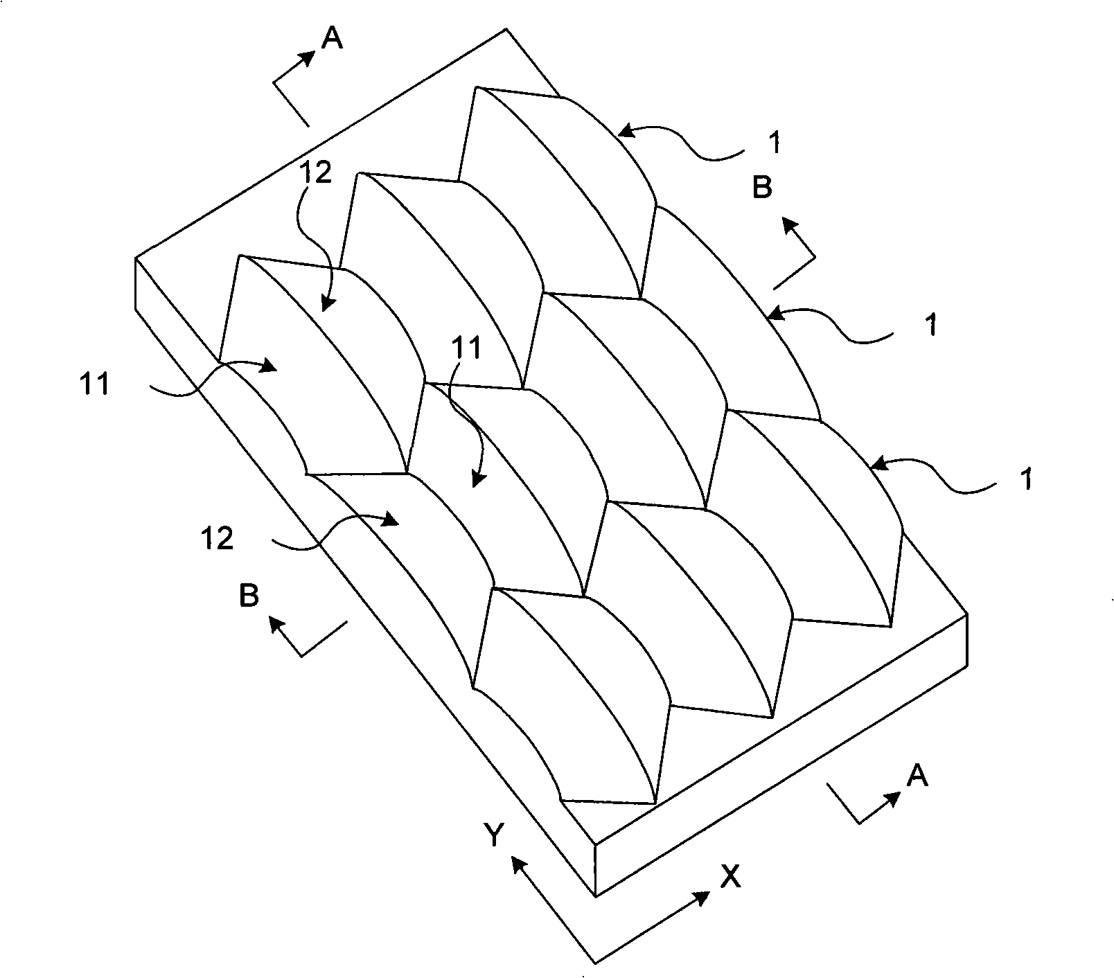
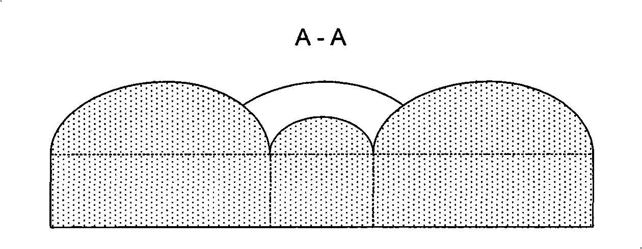
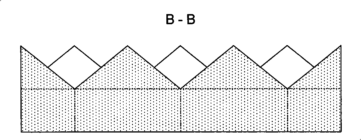
[0026] figure 1 It is a schematic structural diagram of the first embodiment of the enhanced prism film of the present invention. Such as figure 1 As shown, the enhanced prism film of this embodiment includes several cylindrical bodies 1, each cylindrical body 1 is composed of several first frustums 11 and second frustums 12, and the first frustum 11 and the second frustum 12 are connected in sequence And extend along the first direction X, the conical bottom of each first conical frustum 11 is docked with the conical bottom of the adjacent second conical frustum 12, and the conical top of each first conical frustum 11 is connected to the conical bottom of the adjacent second conical frustum 12. The cone tops are butted to form a cylindrical body similar to a straight thread structure. Several cylindrical bodies 1...


PUM

PropertyMeasurementUnit
widthaaaaaaaaaa
widthaaaaaaaaaa
heightaaaaaaaaaa

Abstract

The present disclosure relates to an enhanced prism film comprising a plurality of column-like elements extending in a first direction. The plurality of column-like elements abut against one another in a second direction different form the first direction so as to form a light exiting surface of the enhanced prism film with converging effect in both the first and second direction.

Description

technical field [0001] The invention relates to an optical structure film of a backlight source in a liquid crystal display, in particular to an enhanced prism film. Background technique [0002] At present, the backlight source in the liquid crystal display is provided with an optical structure film, and the optical structure film plays the role of enhancing the brightness and expanding the viewing angle. Figure 11 It is a structural schematic diagram of an optical structural film of a backlight source in the prior art, and it is an edge lighting structural form. Such as Figure 11 As shown, the optical structural film of the backlight mainly includes a light guide plate 10, a diffusion film 20 and a prism film 30. The light source 40 located on the side of the optical structural film provides illumination light 50. After the light emitted from the prism film 30 enters the prism film 30, the prism film 30 concentrates the light emitted from the prism film 30 in a smaller a...

Claims


Application Information

Patent Timeline
Patent Type & Authority Patents(China)
IPC IPC(8): G02B6/00G02F1/13357
CPCG02B5/045G02B6/0053
Inventor 欧盛佳张奇
Owner BOE TECH GRP CO LTD
Why Eureka
Try Eureka