Flange assembly of oil feeding device for vehicle and electrical plug

A technology of oil supply device and electric plug, which is applied in the direction of vehicle components, power devices, and the arrangement combined with fuel supply of internal combustion engines, etc., which can solve the limitation of universality of flange components, high cost of molds, difficulty in meeting the requirements of function definition, etc. question

Active Publication Date: 2010-09-15
UNITED AUTOMOTIVE ELECTRONICS SYST
View PDF1 Cites 0 Cited by
  • Summary
  • Abstract
  • Description
  • Claims
  • Application Information

AI Technical Summary

Problems solved by technology

[0005] 1. The electrical interface of the flange assembly of the vehicle oil supply device is injection molded together with the flange, so the mold structure of the entire flange assembly is relatively complicated, and the mold cost is relatively high
Moreover, the flange assembly cannot be changed due to the fixed electrical interface, and the versatility of the flange assembly is limited. Therefore, the usage of each flange assembly is limited, and the unit price of the flange assembly parts is relatively high.
[0006] 2. The orientation of the electrical interface of the flange component is fixed, the definition of the pin function of the electrical interface is fixed, and it cannot be adjusted at will. The requirements of the definition of the pin function of the interface limit the versatility and flexibility of the application of flange components. Usually, it is necessary to continuously develop new flange components according to the specific interface requirements of customers, and the product development cost is high.
[0007] 3. The pin orientation of the fixed electrical interface of the flange assembly limits the direction of the wiring harness on the inner surface of the flange, and the degree of freedom of wiring harness layout is limited, which is not conducive to the design and optimization of the wiring harness assembly connection process
The assembly operation of the wiring harness is sometimes difficult, which affects the production cycle and low production efficiency

Method used


Image

  • Flange assembly of oil feeding device for vehicle and electrical plug
  • Flange assembly of oil feeding device for vehicle and electrical plug
  • Flange assembly of oil feeding device for vehicle and electrical plug

Examples


Embodiment Construction

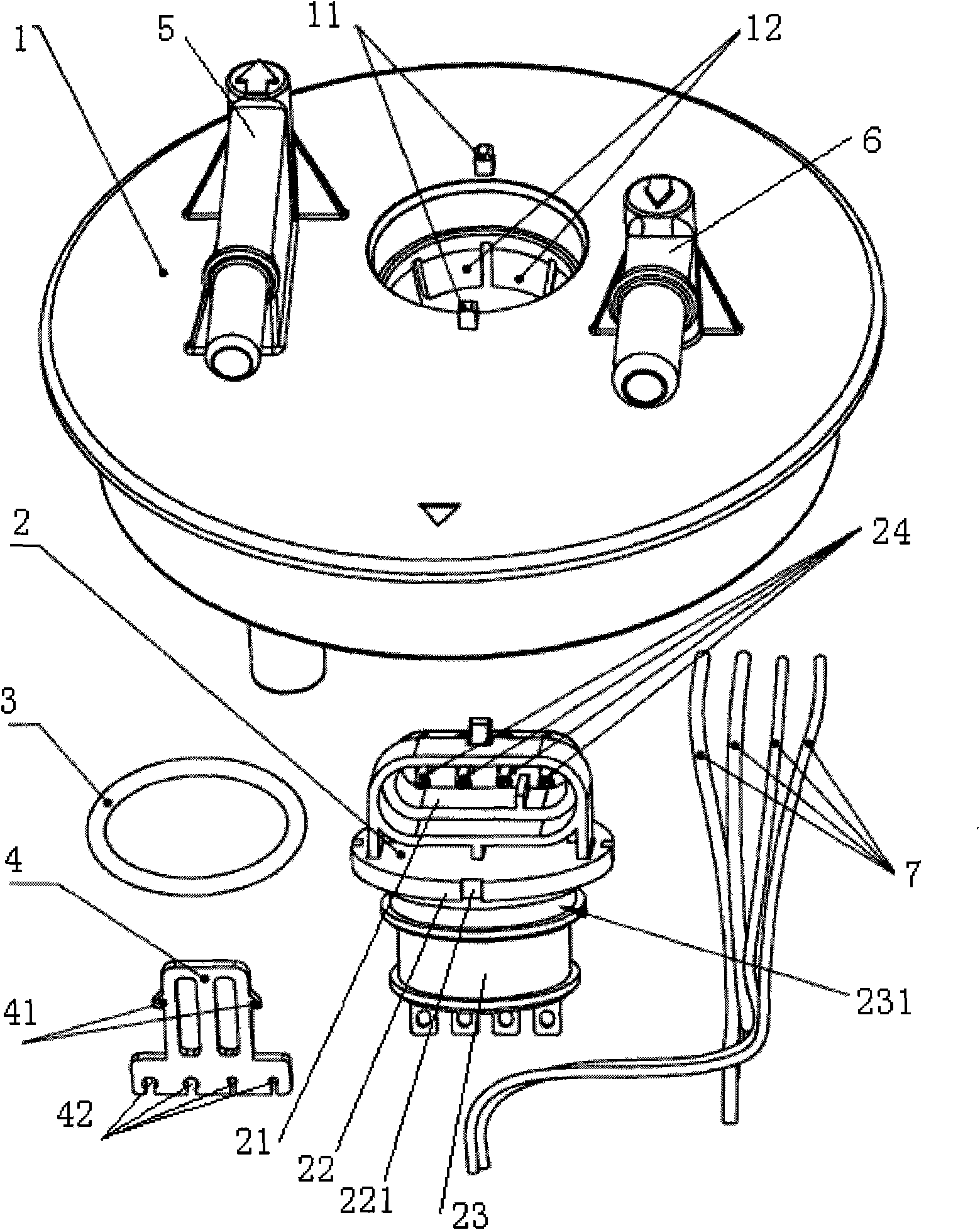
[0030] An embodiment of the flange assembly of the vehicle oil supply device of the present invention is as follows: image 3 , Figure 4 As shown, it includes a flange 1, an oil outlet pipe 6, an oil return pipe 5, an electric plug 2, an O-ring 3, a wire harness clip 4, etc.; the flange 1 is provided with a round hole for installing an electric plug, and the method There are two protrusions 11 arranged symmetrically with the center of the circle on the periphery of the electric plug installation hole on the outside of the blue plate, and elastic grips 12 are arranged on the periphery of the electric plug installation hole on the inner surface of the flange; the electric plug 2 includes a positioning circular plate 22, Power interface 21, wire harness interface 23, a plurality of metal inserts 24, the power interface 21 is located outside the positioning circular plate 22, the wire harness interface 23 is located inside the positioning circular plate 22, the positioning circul...


PUM


Abstract

The invention discloses a flange assembly of an oil feeding device for a vehicle and an electrical plug. A concept of modular design is adopted; the electrical plug and a harness clamp are separated from the traditional flange assembly independently and become independent parts respectively; the electrical plug is formed by plastic injection molding independently and embedded with metal insertingpieces to achieve electrical conduction function; a flange plate is provided with a mounting interface of the electrical plug; the mounting interface provides multiple mounting directions for selection so that a plurality of groups of assembly position relations are provided when the electrical plug and the flange plate are assembled, and particularly, one group of suitable assembly state can be selected according to a specific application occasion; the harness clamp is also an independent part and assembled on the electrical plug to fix harnesses; the electrical plug is provided with a plurality of clamping groove positions for assembling the clamp; and the harness clamp and the electrical plug have a plurality of groups of assembly position relations to aid to realize the combinations of multiple electrical pin function definitions.

Description

technical field [0001] The invention relates to a fuel supply device for a vehicle engine, in particular to a flange assembly and an electric plug of a fuel supply device for a vehicle. Background technique [0002] Fuel supply devices for vehicles such as figure 1 As shown, it usually includes a fuel tank 11, an oil pump bracket assembly, a fine filter 31, a fuel injector 32, and a liquid level sensor. The liquid level sensor is used to detect the liquid level in the fuel tank. The oil pump bracket assembly includes an oil storage barrel 21 , oil pump 22, primary filter 122, flange assembly 28, pressure regulating valve 26, jet pumps 271, 272, etc. The oil from the oil pump 22 enters the fine filter 31 through the flange oil outlet pipe, and then through the pressure regulating valve 26 to adjust the pressure, the fine filter 31 A part of the oil output goes through the fuel injector 32 to remove the fuel consumption of the engine, and the rest is oil return. The oil retur...

Claims


Application Information

Patent Timeline
Patent Type & Authority Applications(China)
IPC IPC(8): B60K15/077
Inventor 罗平亮邓华林祁泾平柳朝华钟艳陈超华康泰胜黄佳健
Owner UNITED AUTOMOTIVE ELECTRONICS SYST
Why Eureka
Try Eureka