Battery combination cover and battery

A technology for combining a cover and a battery is applied to the battery. It can solve the problems of battery capacity reduction, increase internal space, etc., and achieve the effect of increasing battery capacity, reducing height, and compact overall structure

Active Publication Date: 2011-03-30
SHENZHEN BAK POWER BATTERY CO LTD
View PDF6 Cites 6 Cited by
  • Summary
  • Abstract
  • Description
  • Claims
  • Application Information

AI Technical Summary

Problems solved by technology

Due to the structural design limitations of the assembly seat, the height of the explosion-proof cover assembly is increased. When this explosion-proof cover assembly is applied to the battery, it will undoubtedly increase the internal space of the battery cylinder. In this way, only Smaller battery cells are installed, resulting in reduced battery capacity

Method used


Image

  • Battery combination cover and battery
  • Battery combination cover and battery
  • Battery combination cover and battery

Examples


Embodiment approach 1

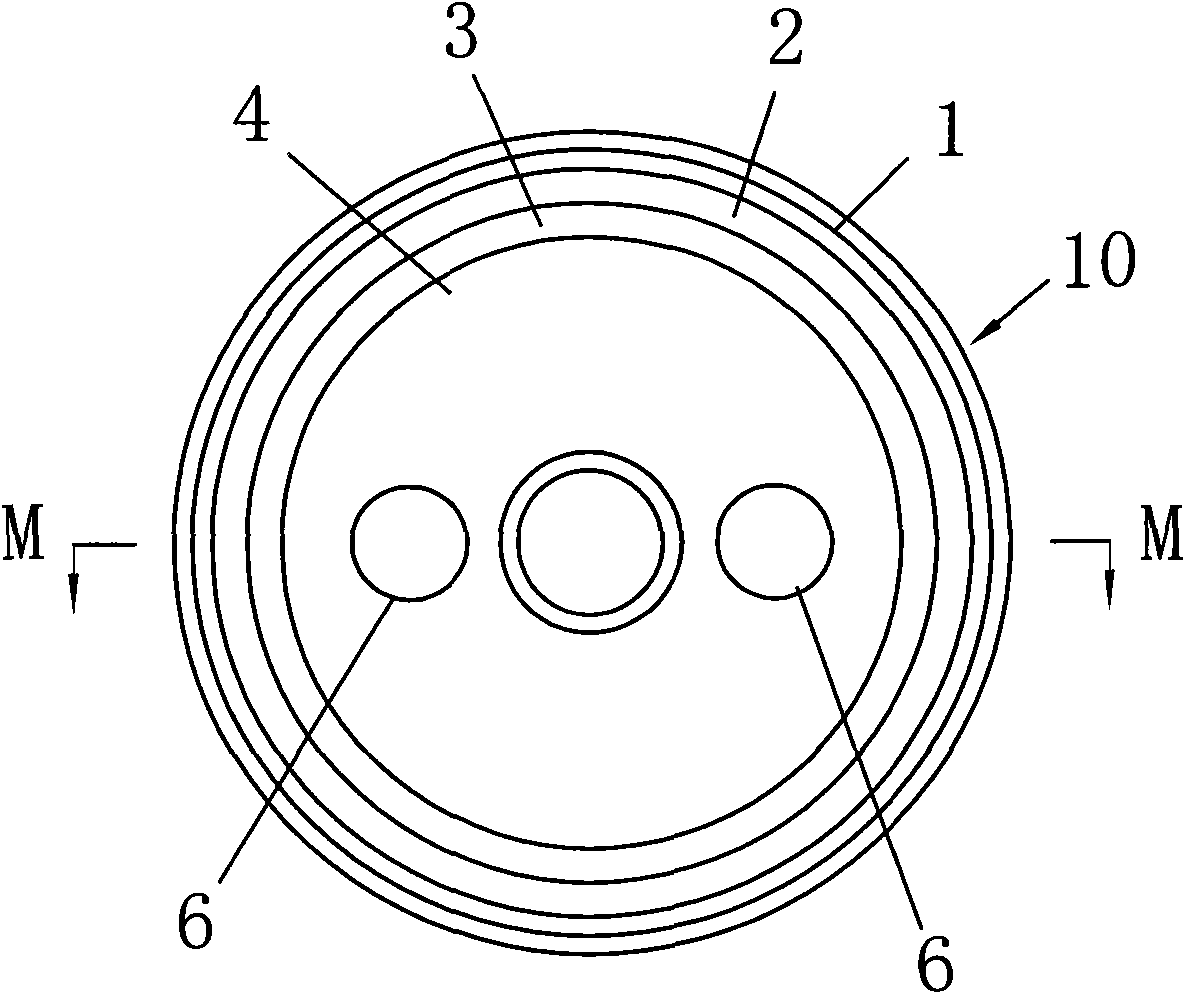
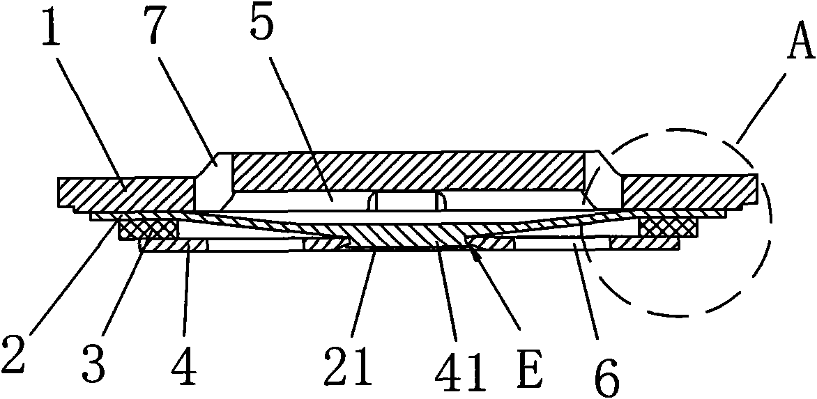
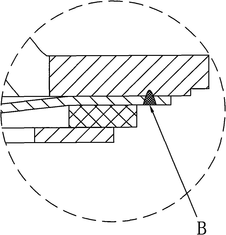
[0033] like Figure 1 to Figure 4 As shown, a battery combination cover 10 includes a top cover 1 , an explosion-proof membrane 2 , a pull plate 4 , and an insulator 3 . A sealed electrical connection is made between the lower surface of the top cover 1 and the explosion-proof membrane 2, and a pressure relief chamber 5 is formed between the top cover 1 and the explosion-proof membrane 2; a pull plate 4 is arranged below the explosion-proof membrane 2, such as figure 2 The middle part of the shown explosion-proof membrane 2 is fixedly electrically connected to the middle part of the pull plate 4; as figure 2 As shown, the insulator 3 is provided in the non-electrical connection area between the peripheral lower surface of the explosion-proof membrane 2 and the peripheral upper surface of the pull plate 4 . Among them, the sealed electrical connection between the top cover 1 and the explosion-proof membrane 2 can be laser welding, high-temperature flame welding, or conductiv...

Embodiment approach 2

[0039] Such as Figure 6 to Figure 9 As shown, a battery combination cover 20 in this embodiment is further improved on the basis of the battery combination cover 10 in the first embodiment. The improvements are as follows: one is that the lower surface of the top cover 1 is provided with a boss 8 for positioning the explosion-proof membrane 2; Welding speed between 2. More importantly, the boss 8 is annular, and the gap between the inner wall of the boss 8 and the periphery of the explosion-proof membrane 2 is used as a laser welding site (such as Figure 8 The place indicated by the middle arrow D), the laser beam goes deep into the gap during welding, of course, in other embodiments, the high-temperature flame can also be used to go deep into the gap, so as to heat the two parts of the top cover 1 and the explosion-proof membrane 2 at the same time to form a deeper The weld pool formed by welding can be greatly improved in sealing and strength. The second is that the per...


PUM


Abstract

The invention relates to a battery combination cover and a battery using the battery combination cover, wherein, the battery combination cover comprises a top cap with a pressure-relief hole, an explosion-prevention film, a pulling plate and an insulator; the lower surface of the top cap is electrically connected with the explosion-prevention film in a sealing mode, and a pressure-relief chamber is formed between the top cap and the explosion-prevention film; the pulling plate is arranged under the explosion-prevention film, and the explosion-prevention film is fixedly and electrically connected with the pulling plate; and the insulator is arranged on a non-electric connecting area between the explosion-prevention film and the pulling plate. Because the top cap and the explosion-prevention film are connected in a direct laminated surface contact manner, the explosion-prevention film and the pulling plate are connected fixedly and electrically in a direct laminated surface contact manner, and the insulator is arranged between the explosion-prevention film and the pulling plate, so that the integral structure of the battery combination cover become compact, thus the height of the battery combination cover is decreased greatly, and the battery capacity is improved.

Description

technical field [0001] The invention relates to a battery combination cover and also relates to a battery. Background technique [0002] At present, the battery generally has a battery combination cover with an explosion-proof function. Chinese patent CN101170168A discloses an explosion-proof cover plate assembly, which is actually a battery combination cover with an explosion-proof function, mainly composed of an assembly seat, a top cover, an explosion-proof membrane, an insulating piece and a pull plate; In the cavity, the cover plate and the explosion-proof membrane are insulated and hermetically fixed by insulating parts. The cover plate and the explosion-proof membrane are electrically connected and form a pressure relief chamber with each other. There is a pressure relief hole on the cover plate, and the explosion-proof membrane It is electrically connected with the pull plate located below it and fixed on the equipment seat after being insulated by the insulator. D...

Claims


Application Information

Patent Timeline
Patent Type & Authority Applications(China)
IPC IPC(8): H01M2/04H01M2/20H01M2/12H01M2/22H01M2/34H01M10/00H01M6/00H01M50/147H01M50/342H01M50/502H01M50/528H01M50/578
CPCH01M2/1223H01M2/0426H01M2/046Y02E60/10H01M50/169H01M50/152H01M50/317Y02P70/50
Inventor 毛焕宇郝焱尚随军郑荣鹏
Owner SHENZHEN BAK POWER BATTERY CO LTD
Why Eureka
Try Eureka