Fully mechanized coal face bracket withdrawing method and withdrawing bracket traction spring exerciser

A technology of fully mechanized mining face and tension device, which is applied to pillars/supports, mining equipment, earth-moving drilling, etc., can solve the problems of long construction period, large materials, time-consuming and labor-intensive, etc. Time saving effect

Active Publication Date: 2010-09-29
BEIJING TIANDI HUATAI MINING MANAGEMENT CO LTD
View PDF5 Cites 22 Cited by
  • Summary
  • Abstract
  • Description
  • Claims
  • Application Information

AI Technical Summary

Problems solved by technology

When the stand is lifted by the single body, people operate at close range, which has great safety hazards and serious damage to the single body
This method of retracting the bracket has a large safety hazard, consumes a lot of materials, is time-consuming and labor-intensive, and has a long construction period

Method used


Image

  • Fully mechanized coal face bracket withdrawing method and withdrawing bracket traction spring exerciser
  • Fully mechanized coal face bracket withdrawing method and withdrawing bracket traction spring exerciser
  • Fully mechanized coal face bracket withdrawing method and withdrawing bracket traction spring exerciser

Examples


Embodiment 1

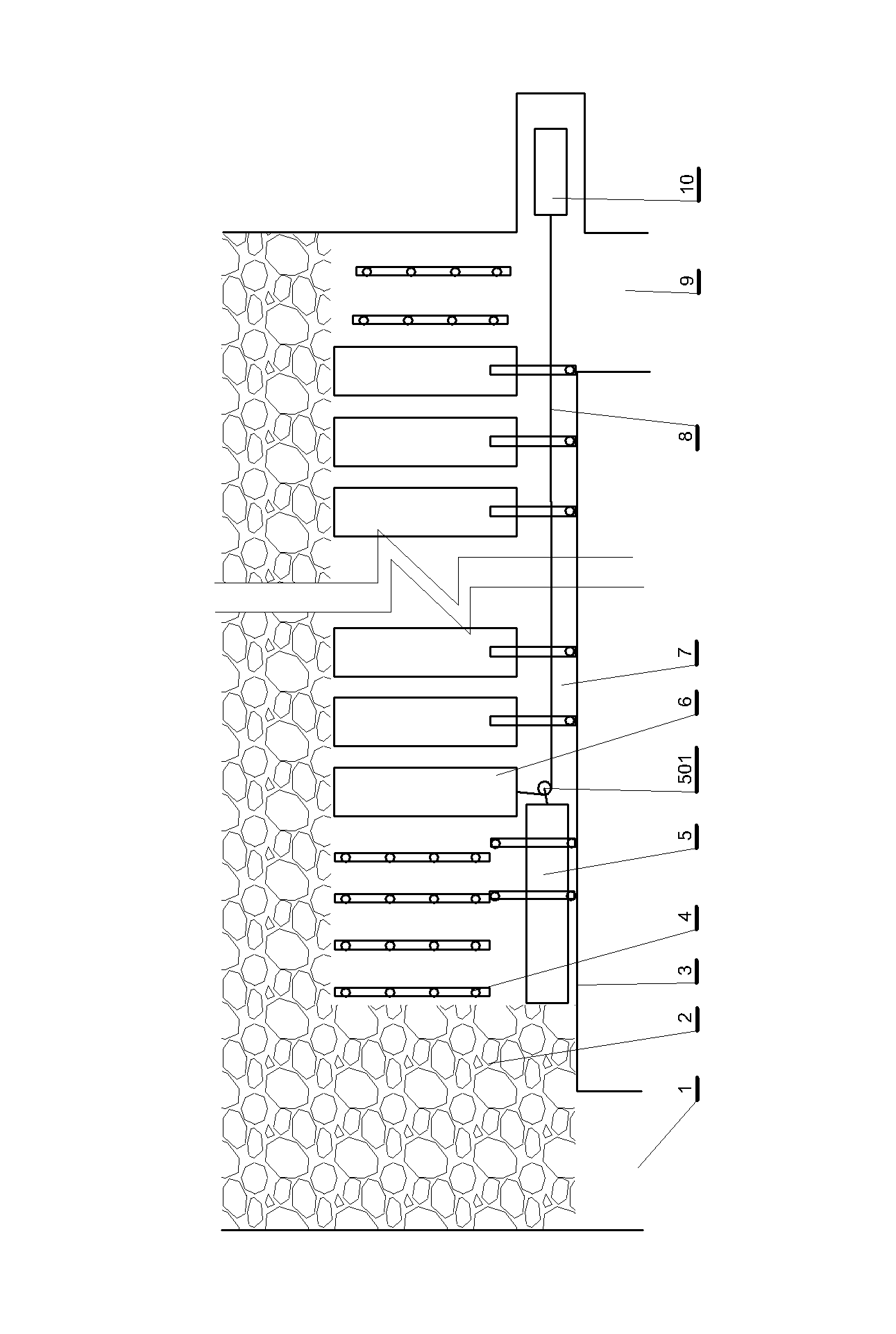
[0028] figure 1 It is a schematic diagram of the retraction of the support in the fully mechanized mining face. In the figure, track channel 1, withdrawal channel 7 and transportation channel 9 form the original fully mechanized mining channel, and the withdrawal channel is the original fully mechanized mining face. Since the coal mining of this working face has been completed, the coal seam is cut into a goaf In area 2, the position where cutting can no longer be continued is the coal side 3 of the stop mining line, and the supports are erected side by side on the side of the evacuation passage before evacuation. figure 1 Middle 6 is the position before stent withdrawal. In order to ensure safety, each support must be connected to the top before evacuation, and it will only be lowered when it is the turn to evacuate. Also will use single hydraulic prop 4 to support around this support before lowering, prevent from collapsing. After lowering, use the two-speed winch 10 to e...

Embodiment 2

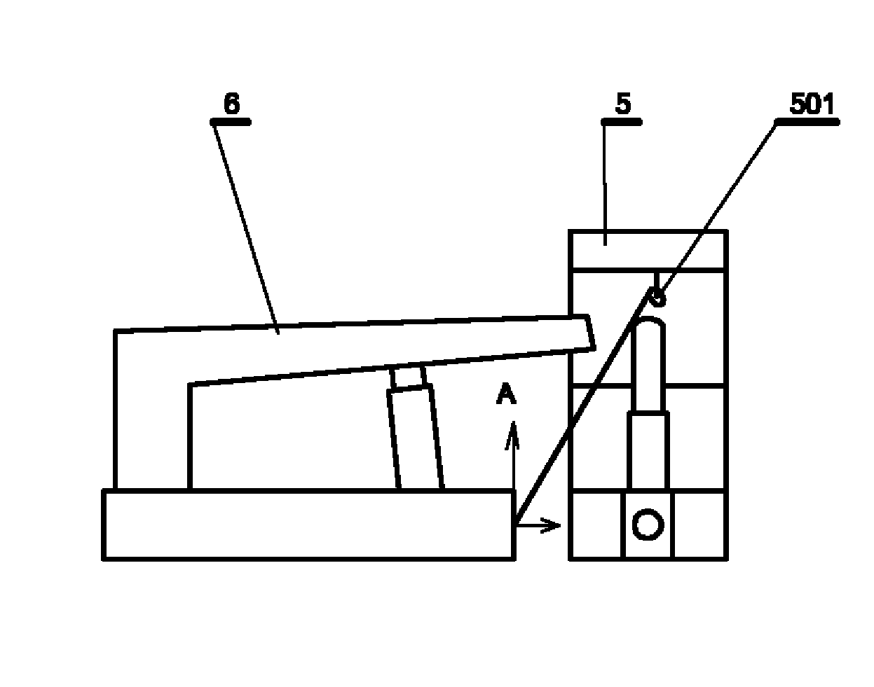
[0048] This embodiment is the key tool traction tensioner used in the method described in embodiment one, as Figure 5 shown. This embodiment includes: a beam 1101 fixed with a traction pulley, the middle part of the beam has a connecting beam 1102 perpendicular to the beam and fixedly connected with the beam, the other end of the connecting beam is fixedly connected with a short beam 1104, the The short beam is parallel to the cross beam, and forms a gate shape with the cross beam and the connecting beam. The width of the opening of the gate shape is consistent with the base of the hydraulic support. There is a pin hole 1103 at the corresponding position of the pin hole.

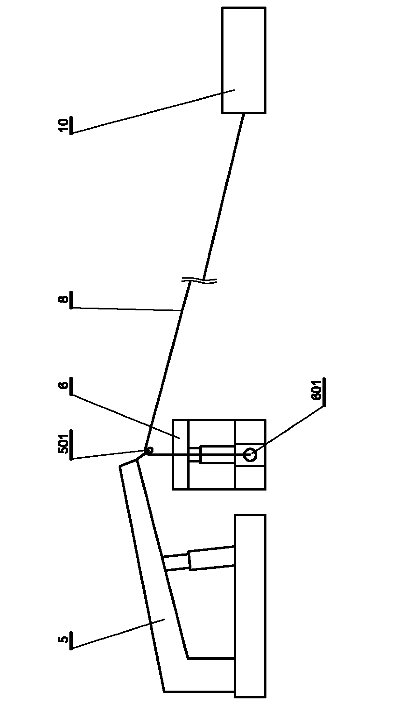
[0049] Such as Figure 6 Forces on the traction pulley shown. The figure shows that the traction pulley is subjected to large loads in two directions: the directions of arrows B and C. It can be concluded from the force situation that the traction pulley cannot be directly installed on the head of the c...

Embodiment 3

[0052] This embodiment is an improvement of the second embodiment, and is a refinement of the second embodiment about the tensioner. A reinforcing rib 1105 is provided between the beam and the connecting beam described in this embodiment.

[0053] In this embodiment, triangular reinforcing ribs are arranged on the beams and connecting beams according to the stress situation.


PUM


Abstract

The invention relates to a fully mechanized coal face bracket withdrawing method and a withdrawing bracket traction spring exerciser, in particular to a process for withdrawing a bracket after the backstoping of a working face is finished in a mine, and the traction spring exerciser used in the withdrawing process. The traction spring exerciser comprises a section of beam fixed with a traction pulley, wherein the middle part of the beam is provided with a tie beam which is vertical to and fixedly connected with the beam; the other end of the tie beam is fixedly connected with a short beam; the short beam is parallel to the beam and forms a door shape with the beam and the tie beam; a width at an opening of the door shape is matched with a base of a hydraulic bracket; and a position, matched with a pin hole on a cylinder lever head part of a traction cylinder of the hydraulic bracket, on the middle part of the tie beam is provided with the pin hole. In the fully mechanized coal face bracket withdrawing method, the traction spring exerciser is utilized, and a cylinder lever of the traction cylinder which cannot be subjected to a radial force originally is used for transversely pulling the hydraulic bracket, so the whole withdrawing process is very simple, manpower and materials are saved and withdrawing security is ensured.

Description

technical field [0001] The present invention relates to a support retraction method of a fully mechanized mining face and a support traction device for retraction, and is a process method for retracting a support after a working face in a mine is withdrawn and the traction device used in the retraction process method. Puller. Background technique [0002] After the fully mechanized mining is completed, all equipment on the working face shall be evacuated from the working face according to the sequence: shearer, scraper conveyor, support, etc. Since the stent is withdrawn last, the risk is greater. Especially because of the narrow working surface, it is more dangerous to move the stent from the aligned position to the retraction channel, which is usually called withdrawing the stent, and it also increases the difficulty of evacuation due to safety considerations. In the withdrawal of working face equipment, the withdrawal of support is a key link that affects the progress a...

Claims


Application Information

Patent Timeline
Patent Type & Authority Applications(China)
IPC IPC(8): E21D15/60
Inventor 徐继民李国臣王立中李印楼徐继安
Owner BEIJING TIANDI HUATAI MINING MANAGEMENT CO LTD
Why Eureka
Try Eureka