A load restraint assembly

A technology of assembly and locking components, applied in the direction of load fixing, reel unit transportation, vehicles for freight, etc., can solve the problem that the pallet cannot be used, etc.

Inactive Publication Date: 2010-09-29
FERRARI INVESTMENTS
View PDF11 Cites 11 Cited by
  • Summary
  • Abstract
  • Description
  • Claims
  • Application Information

AI Technical Summary

Problems solved by technology

On the return trip, the pallet cannot be used due to the weight of the Robo rack unit and the space it occupies on the pallet

Method used


Image

  • A load restraint assembly
  • A load restraint assembly
  • A load restraint assembly

Examples


Embodiment Construction

[0057] The following description is used in the context of a pallet of a truck carrying a load in the form of coiled steel strip, where the coil is placed sideways (i.e., on the outer circumference of the coil) on the pallet so that the centerline of rotation of the coil is vertical in the length direction of the pallet.

[0058] The following description is also used in the context of pallets for trucks and also carrying long loads on pallets such as bundles of steel bars, steel plates, channels and steel pipes.

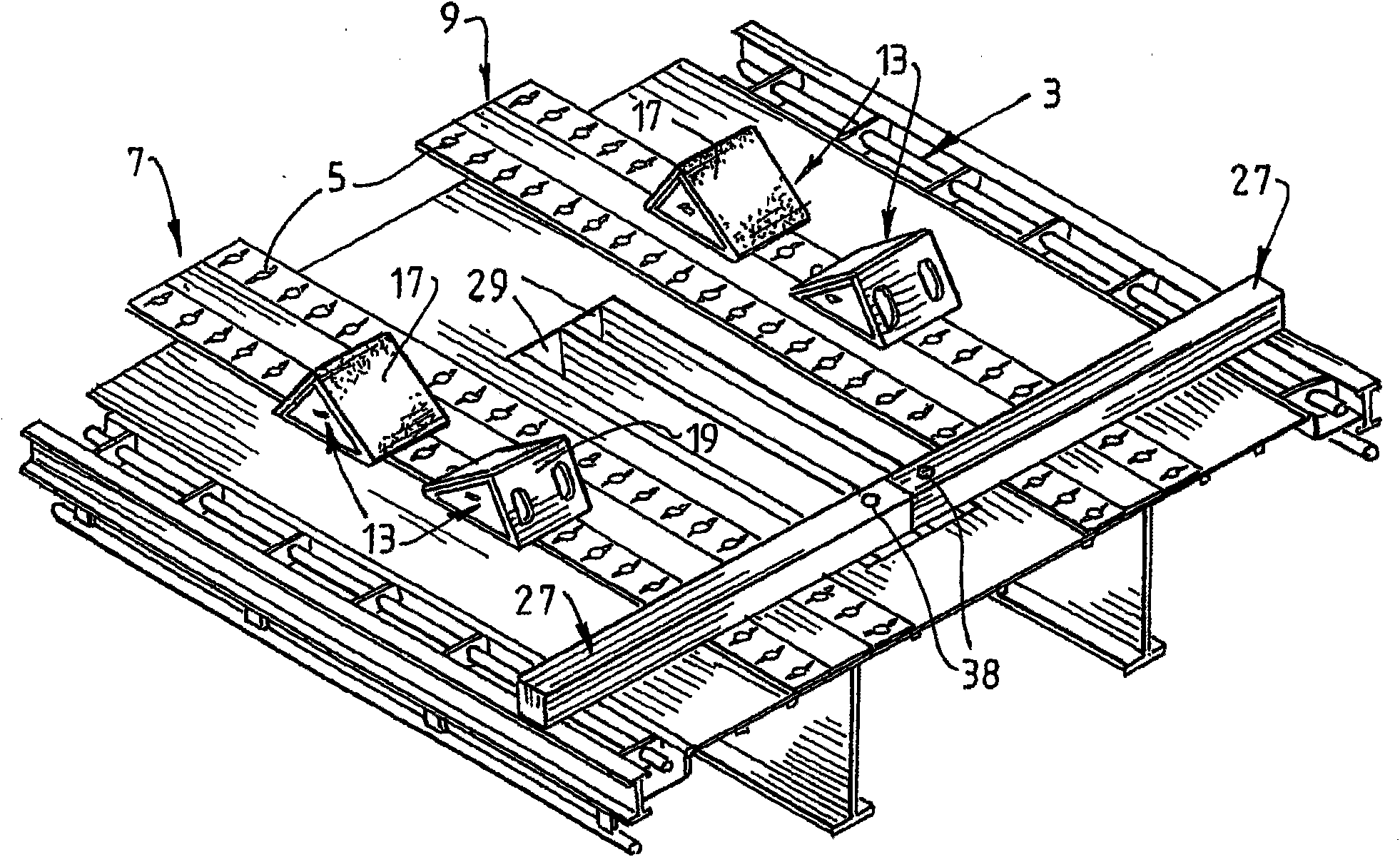
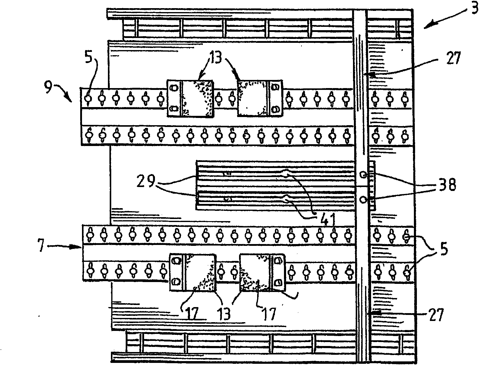
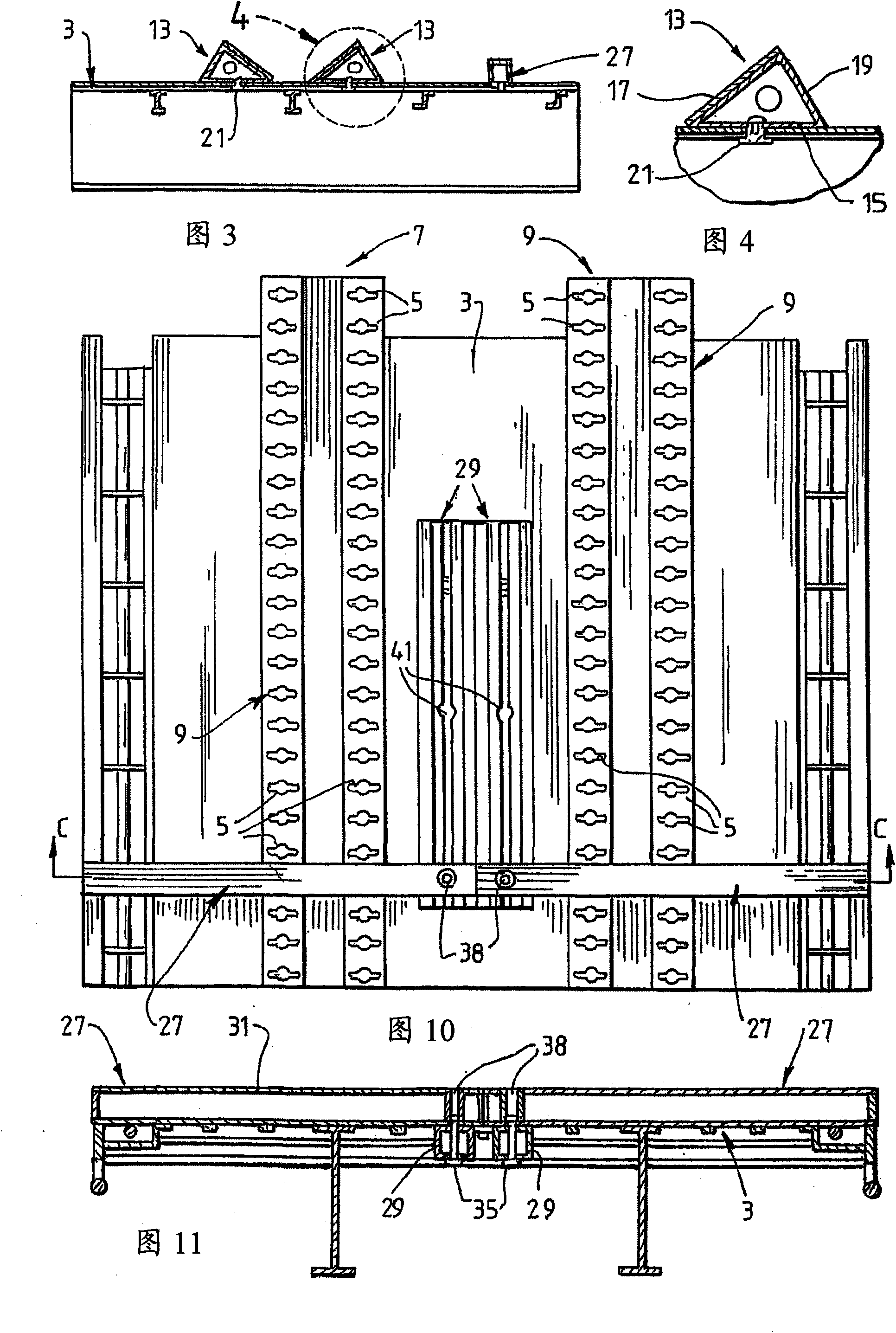
[0059] figure 1 The tray 3 shown in has 4 parallel rows of openings cut in the tray in the form of keyholes 5 . The keyholes 5 in each row have a constant interval. Typically, the center-to-center spacing of the keyholes is 100 cm. The choice of spacing is entirely a function of the load carried on the pallet. This interval is not necessarily constant.

[0060] The keyholes 5 of each row are arranged in two pairs of keyhole rows. The keyhole rows in each pair ...


PUM


Abstract

An assembly for locating and / or restraining a load carried on a tray of a truck or other vehicle is disclosed. The assembly comprises at least one line of keyholes in the tray at spaced intervals along at least a part of the length of a tray. The assembly also comprises at least one chock for locating and / or restraining a load against forward or rearward movement on the tray, with the chock having a locking member that is adapted to be received in the keyholes so that the chock can be supported and retained in a selected position on the tray. The assembly also comprises at least one bearer for locating and supporting a load, such as long products, on the tray.

Description

technical field [0001] The present invention relates to an assembly for positioning and / or restraining a load carried on the tray of a truck or other conveyance. [0002] The invention relates particularly, but not exclusively, to an assembly for positioning and / or restraining a load in the form of a coil of metal strip, such as steel strip. Background technique [0003] Metal coils are usually heavy (ranging from 2 to 18 tons, but most commonly between 4 and 12 tons) and difficult to handle. An important consideration for transporting metal coils is positioning and then securely restraining the coils on the pallet of the truck. Metal coils are typically shipped on their sides (ie, standing on the outer circumference of the coil) to facilitate loading and unloading the coil from a truck pallet by a forklift or other lifting device. This is an inherently unstable positioning for a metal coil and, given the weight of the coil, is a potentially very unsafe way of transporting...

Claims


Application Information

Patent Timeline
Patent Type & Authority Applications(China)
IPC IPC(8): B60P3/035B60P7/12B60P7/15
CPCB60P3/035B60P7/12
Inventor 皮特·沃伦·法拉利
Owner FERRARI INVESTMENTS
Why Eureka
Try Eureka