Sensing system and method

A sensing system and sensing element technology, applied in the field of sensing systems, can solve problems such as unsatisfactory technology, real-time sensors, impractical and time-consuming continuous monitoring

Inactive Publication Date: 2010-09-29
PARAMATA
View PDF0 Cites 3 Cited by
  • Summary
  • Abstract
  • Description
  • Claims
  • Application Information

AI Technical Summary

Problems solved by technology

This can make such systems expensive and time-consuming to install, while real-time, continuous monitoring of sensors is practically impractical
[0003] A disadvantage of known s

Method used


Image

  • Sensing system and method
  • Sensing system and method
  • Sensing system and method

Examples


Embodiment Construction

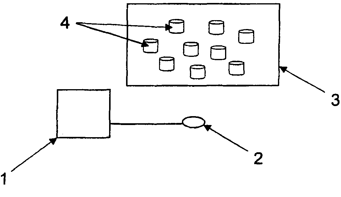
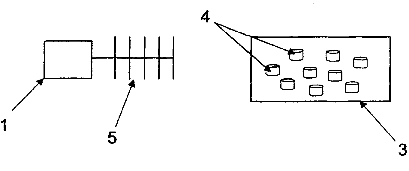
[0029] see figure 1 , showing a schematic diagram of a wireless transceiver 1 with an antenna 2 . A part of the material 3 (for example, a polymer material) has a matrix structure in which a plurality of sensing elements 4 are embedded such that the sensing elements 4 are dispersed within the matrix material 3 and covered by the matrix material 3 around. The sensing element 4 has electron distribution and / or transport properties that change in response to changes in the physical or chemical properties of the material. This behavior results in a change in a radio frequency (RF) signal (eg a microwave signal) transmitted from the transceiver 1 via the antenna 2 to interrogate the matrix material 3 , so that the change in the material can be determined from the received signal. In this way, the sensing element 4 allows non-invasive, intrinsic sensing of changes in the properties of the material.

[0030] The radio transceiver 1 is constructed to generate a modulated radio freq...


PUM


Abstract

A sensing system comprises a material having a matrix structure in which a plurality of sensing elements are embedded, the sensing elements having electron distribution and/or transport properties that change in response to a change in a physical or chemical property of the material. The sensing system further comprises a receiver, including an antenna, the receiver arranged to receive a source RF signal and a returned RF signal, the returned RF signal being received from the material. A change in the electron distribution and/or transport properties of the sensing elements cause the source RF signal to change, such that a change in a property of the material can be determined from the returned RF signal. A corresponding method of sensing a change in a property of a material is also provided.

Description

technical field [0001] The present invention relates to sensing systems and methods. Background technique [0002] Structural health monitoring (SHM) is an area of ​​technology attracting increasing attention in industries such as civil, structural and aerospace engineering technologies. The goal of SHM is to use sensors to collect data about critical structural elements in order to provide indicators of anomalies detected in structures to monitor their reliability and safety. Current SHM systems require the installation of one or more sensors at significant points of any structure of interest, the type of sensor depending on the particular parameter of interest to be sensed. This can make such systems expensive and time-consuming to install, while real-time, continuous monitoring by sensors is practically impractical. [0003] One disadvantage of known systems is that the composite materials used in modern aircraft render current SHM technology obsolete, creating demands ...

Claims


Application Information

Patent Timeline
IPC IPC(8): G01D1/00G01M1/00G08C17/02G01M5/00
CPCG01N22/02H04Q2209/40H04Q2209/845G01D5/16H04Q9/00G01D5/12G01N35/00871G01M5/0033G01M5/0083G01N2011/0066G01N2011/0073
Inventor 克里斯托弗·R·洛昆廷·坦诺克艾德里安·史蒂文森卡里什玛·杰恩
Owner PARAMATA
Why Eureka
Try Eureka