Clamping device having mechanical damping for a traction engine drive

A technology of tensioning device and transmission device, which is applied in the direction of transmission device, mechanical equipment, belt/chain/gear, etc., and can solve the problem of increasing the edge load of the sliding support part, etc.

Inactive Publication Date: 2010-10-20
SCHAEFFLER TECH AG & CO KG
View PDF4 Cites 4 Cited by
  • Summary
  • Abstract
  • Description
  • Claims
  • Application Information

AI Technical Summary

Problems solved by technology

Owing to the tensions required in the given assembly situation, the balancing can only be achieved

Method used


Image

  • Clamping device having mechanical damping for a traction engine drive
  • Clamping device having mechanical damping for a traction engine drive

Examples


Embodiment Construction

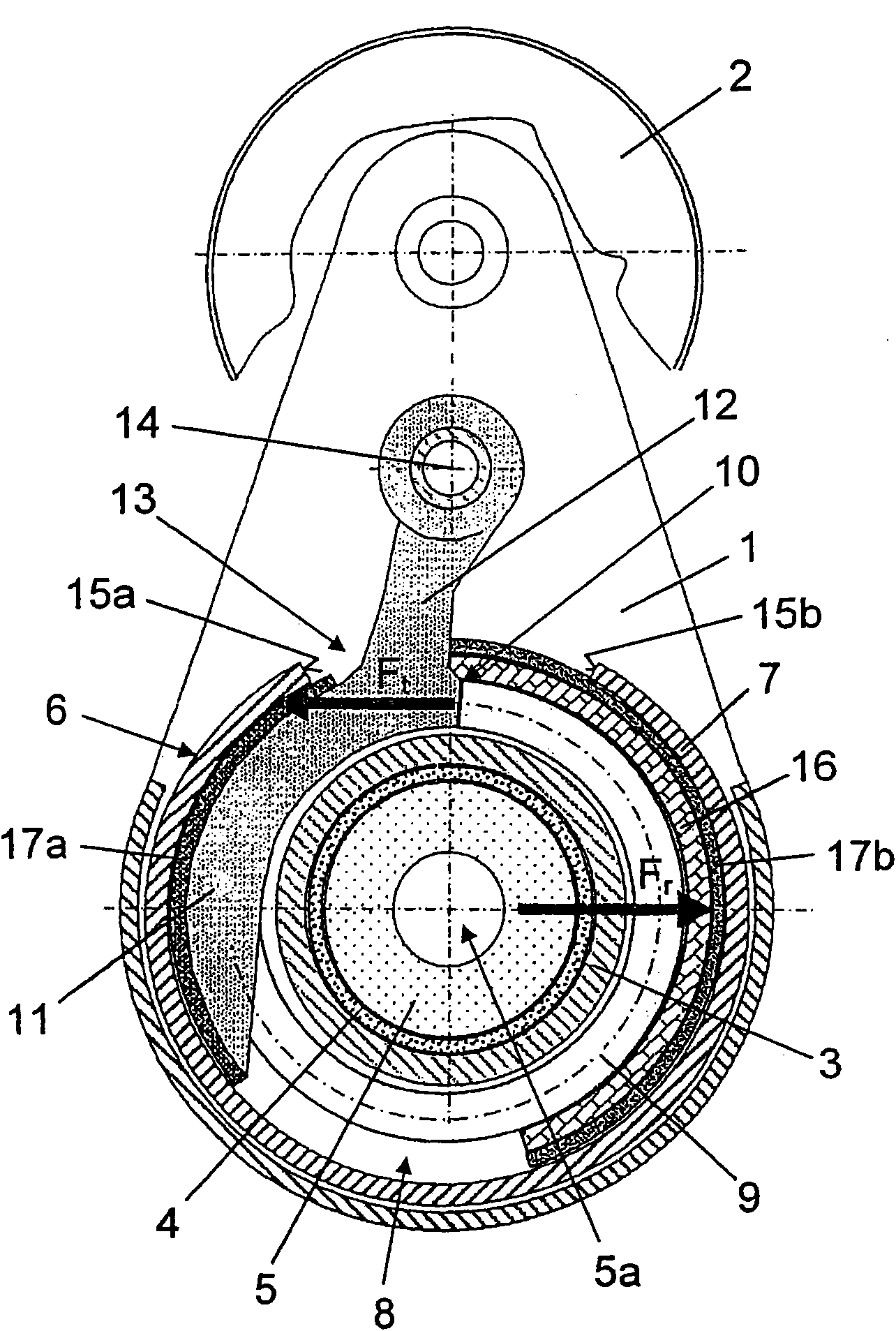
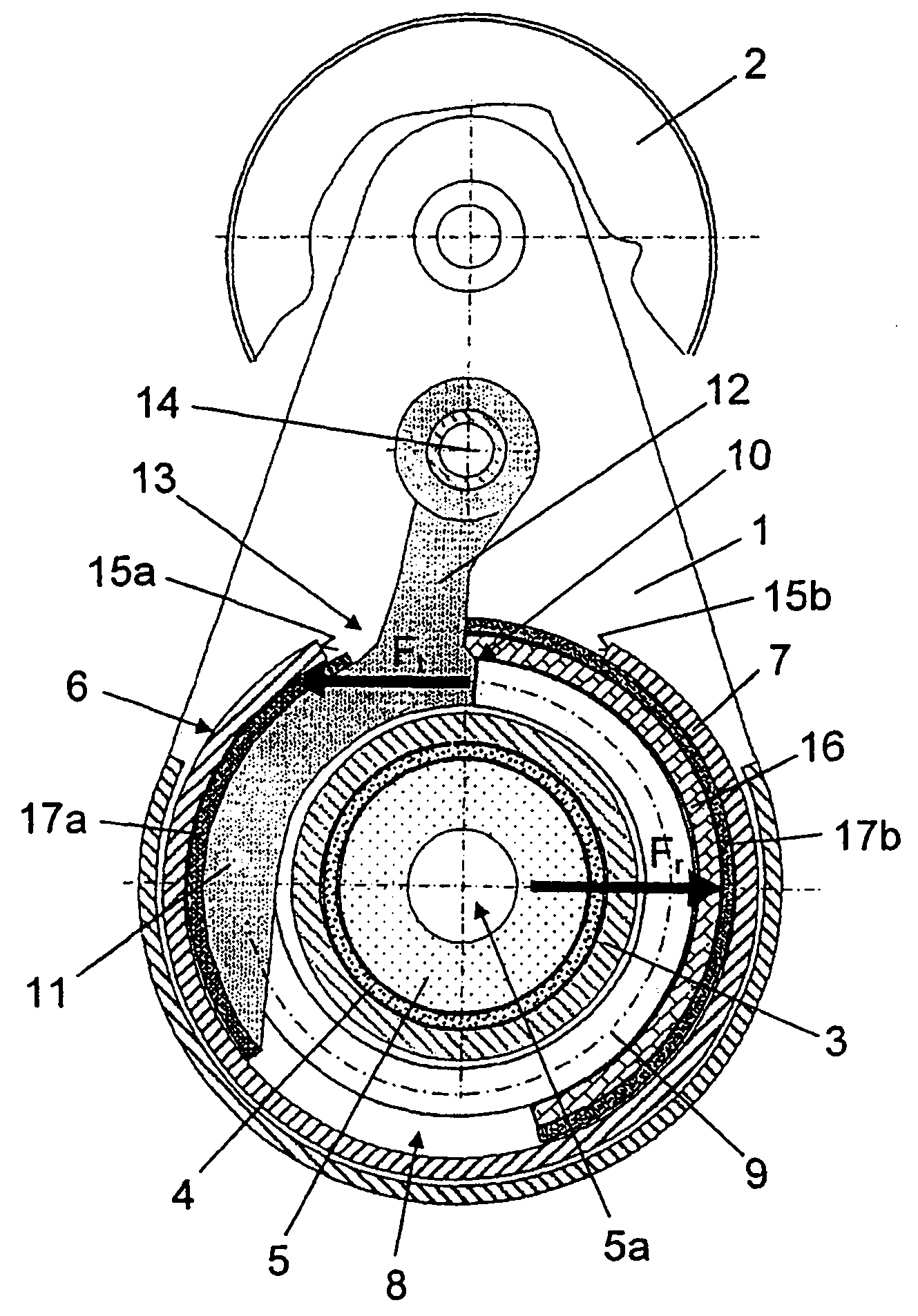
[0020] The tensioning device for the traction mechanism drive (not shown in detail) has a known tensioning roller support 1 constructed in the manner of a single-arm lever, which supports a tensioning roller 2 at its free end. The other end of the tensioning roller bracket 1 is rotatably supported by means of a hub-shaped bearing part 3 via a sliding bearing 4 in the form of a bearing sleeve on a centrally arranged bearing pin 5 of a stationary base part 6 which, for its part, is It has a bowl-shaped shape and can be fixed on a supporting component, which can be a motor housing or a transmission housing of a motor vehicle, by means of mechanical fixing elements, such as fixing bolts (which pass through the axial holes 5a of the support bolt 5) body.

[0021] In the annular space 8 formed between the inner contour of the wall 7 of the pot-shaped basic part 6 and the hub-shaped support part 3 of the tensioning roller bracket 1, a torsion spring 9 is arranged concentrically surro...


PUM


Abstract

The invention relates to a clamping device having mechanical damping for a traction engine drive, having a fixed, bowl-shaped base part (6) and a clamping roller carrier (1) having at least one clamping roller (2) and rotatably supported by a sliding bearing (4) on a centrally disposed bearing spindle (5) by means of a hub-shaped bearing part (3), wherein the clamping roller carrier (1) is pretensioned against the base part (6) by means of a torsional spring (9) disposed in the ring space (8) formed between the inner contour of the wall (7) of the bowl-shaped base part (6) and the hub-shaped bearing part (3) of the clamping roller carrier (1) and concentrically encompassing the bearing part (3). Furthermore, according to the invention, the torsional spring (9) in said clamping device is designed as a tabless spring on at least one end thereof, and supports itself by means of the at least one tabless spring end on a first frictional element (11) in the form of a brake shoe, and by means of the other spring end on a bowl-shaped base part (6) of the clamping device, wherein the first frictional element (11) is pivotally supported on the clamping roller carrier (1) by means of a leverarm (12) extending in turn through a cutout (13) in the wall (7) of the base part (6) and is pressed by the spring force by means of the torsional spring (9) against the inner contour of the wall (7)of the bowl-shaped base part (6).

Description

technical field [0001] The invention relates to a tensioning device with mechanical damping for a traction mechanism drive, which has a fixed, cup-shaped base part and has a sliding action on a centrally arranged bearing bolt of the base part. A tensioning roller carrier mounted in rotation by means of a hub-shaped bearing part, the tensioning roller carrier having at least one tensioning roller, wherein the tensioning roller carrier is prestressed relative to the base part by means of a torsion spring arranged on In the annular space formed between the inner contour of the wall of the bowl-shaped base part and the hub-shaped support part of the tensioning roller carrier, the support part is surrounded concentrically. Background technique [0002] Such tensioning devices have been known for a long time in various embodiments. Thus, DE4029940A1 discloses a damping device for a belt tensioning system of the generic type, which has at least one pivotable annular segment suppor...

Claims


Application Information

Patent Timeline
IPC IPC(8): F16H7/12
CPCF16H7/1281F16H7/0831F16H7/1218F16H2007/081
Inventor 约翰·辛格尔克里斯蒂娜·托曼
Owner SCHAEFFLER TECH AG & CO KG
Why Eureka
Try Eureka