Energy storage device with failure detection and automatic reconstruction function and reconstructing method

A technology of energy storage device and fault detection, applied in the direction of automatic disconnection emergency protection device, circuit device, transportation and packaging, etc. Install and ensure the effect of normal operation

Inactive Publication Date: 2012-10-31
HARBIN ENG UNIV
View PDF0 Cites 3 Cited by
  • Summary
  • Abstract
  • Description
  • Claims
  • Application Information

AI Technical Summary

Problems solved by technology

However, due to the fact that the performance of individual energy storage elements cannot be completely consistent, even if the energy storage device works within the safe operating range during use, some energy storage element monomers will be damaged due to excessive operating voltage or current. damage
These damaged energy storage elements connected in series and parallel with other energy storage elements will inevitably affect the overall performance of the energy storage device, or even make it unable to work
The existence of this problem reduces the operational reliability of energy storage devices such as batteries and supercapacitors in actual use.

Method used


Image

  • Energy storage device with failure detection and automatic reconstruction function and reconstructing method
  • Energy storage device with failure detection and automatic reconstruction function and reconstructing method
  • Energy storage device with failure detection and automatic reconstruction function and reconstructing method

Examples


Embodiment approach 1

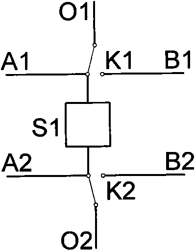
[0051] The energy storage element S1 in the energy storage unit adopts a single energy storage element such as a battery or a super capacitor; the first single-pole double-throw switch K1 and the second single-pole double-throw switch K2 are composed of mechanical contacts of a relay; the first voltage detection line A1 and the second voltage detection line A2 are cables with a shielding layer; the first output line O1 and the second output line O2, as well as the first recombination connection line B1 and the second recombination connection line B2 are copper wires or aluminum stranded wires.

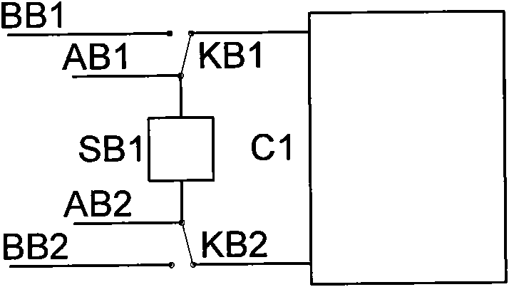
[0052] The energy storage element SB1 in the backup energy storage unit adopts the same energy storage element monomer as the energy storage unit; the first backup single-pole double-throw switch KB1 and the second backup single-pole double-throw switch KB2 are composed of mechanical contacts of the relay; the first The backup voltage detection line AB1 and the second backup voltage det...

Embodiment approach 2

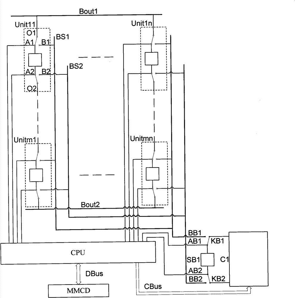
[0071] When the capacity of the energy storage device is large and a large number of energy storage elements such as batteries or supercapacitors are required to be connected in series or parallel, in order to reduce the cost, the energy storage element S1 in each energy storage unit can use several energy storage elements. Body series, parallel structure.

[0072] Others are the same as the above embodiment.

Embodiment approach 3

[0074] All SPDT switches in the energy storage device can be replaced by power electronic devices, such as IGBT, MOSFET, etc. Others are the same as the above embodiment.


PUM


Abstract

The invention provided an energy storage device with failure detection and automatic reconstruction function and a reconstructing method. The energy storage device with failure detection and automatic reconstruction function comprises m*n modular energy storage units with same structures, a standby energy storage unit, a first output bus, a second output bus, a first reconstruction bus, a second reconstruction bus, a central processing unit, a man-machine conversation device, a data bus and a control bus. Aiming at energy storage devices formed by the serial connection and parallel connectionof a plurality of energy storage elements, such as a storage battery pack, a super capacitor pack and the like, the adverse effects brought by singled damaged energy storage element on the whole device is eliminated, and the operation reliability of the energy storage device can be improved.

Description

technical field [0001] The invention relates to an energy storage device in the field of electrical engineering, in particular to an energy storage device composed of a plurality of modularized energy storage units through a unique connection method. Background technique [0002] With the development of energy storage technology, energy storage devices have been widely used in power systems and other industrial occasions. At present, energy storage devices such as battery energy storage and supercapacitor energy storage are widely used. Due to the low voltage and limited capacity of energy storage elements such as batteries and supercapacitors, a large number of energy storage elements are required to be connected together through series and parallel structures to form a large-capacity, high-voltage energy storage device. , such as battery packs or supercapacitor packs, to meet the load's requirements for the working voltage and capacity of the energy storage device. Howeve...

Claims


Application Information

Patent Timeline
Patent Type & Authority Patents(China)
IPC IPC(8): H02J15/00H02J7/00H02J9/06H02H3/06
CPCY02B70/30Y04S20/20
Inventor 张强赵凯岐刘政宇张文义张敬南程鹏
Owner HARBIN ENG UNIV
Why Eureka
Try Eureka