Improvements in and relating to logarithmic detectors

A technology of logarithmic detector and amplifier, applied in demodulator of amplitude modulation oscillation, simultaneous amplitude and angle demodulation, balance device of modulation conversion, etc.

Active Publication Date: 2010-11-24
道康股份公司
View PDF0 Cites 8 Cited by
  • Summary
  • Abstract
  • Description
  • Claims
  • Application Information

AI Technical Summary

Problems solved by technology

[0014] Embodiments of the present invention aim to solve problems related to prior art logarithmic amplifiers, whether discussed here or not

Method used


Image

  • Improvements in and relating to logarithmic detectors
  • Improvements in and relating to logarithmic detectors
  • Improvements in and relating to logarithmic detectors

Examples


Embodiment Construction

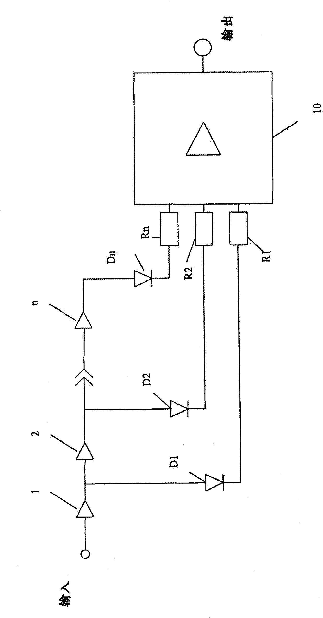
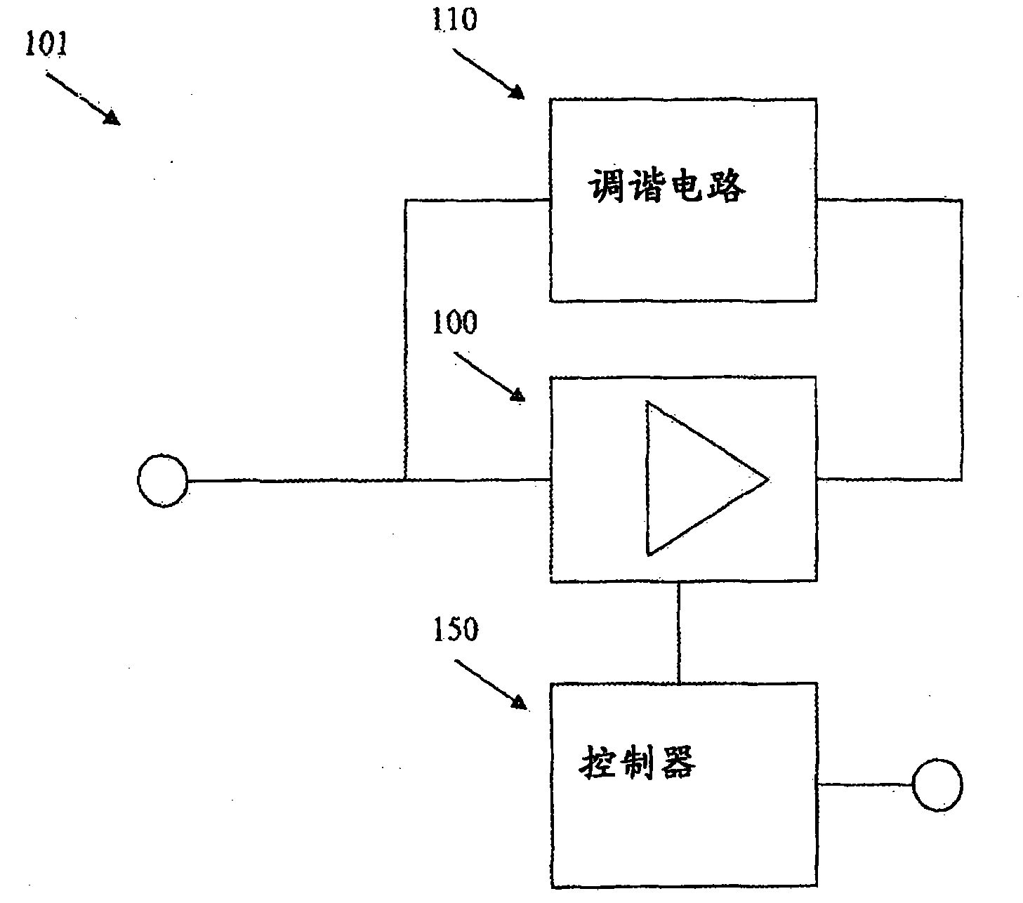
[0039] image 3 Shows the first embodiment of the present invention. This embodiment includes a gain element 100 to which the input signal is applied. A tuning circuit 110 is provided as a feedback circuit connecting the output of the gain element 100 to the input of the gain element 100, the tuning circuit 110 acting to set the operating frequency of the circuit.

[0040] The entire circuit is controlled by a controller 150, which is operable to control certain operating parameters of the gain block, and from which the output of the circuit is derived.

[0041] The input to gain element 100 is the signal desired to be detected. The output of the circuit is obtained from the controller 150 . The input is typically a low level RF signal in the presence of electrical noise.

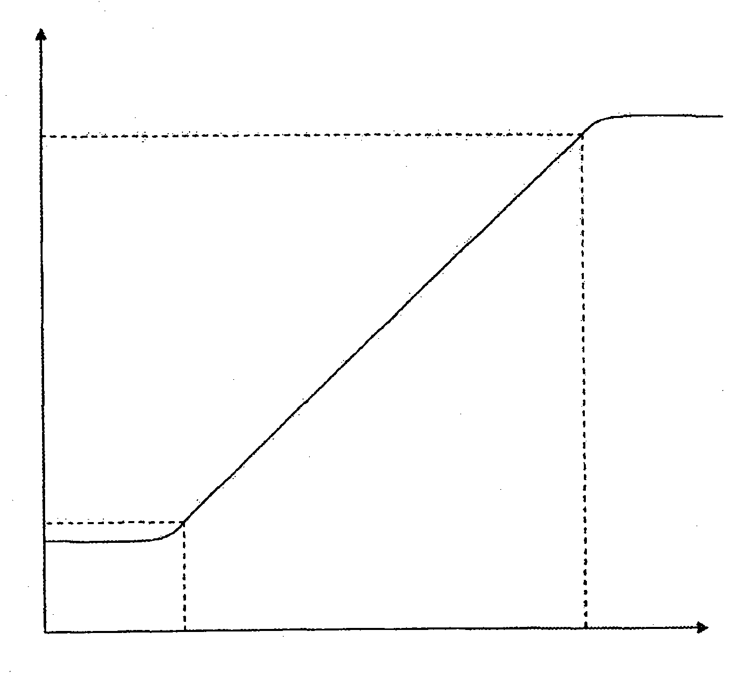
[0042]In 'raw' form, the output signal consists of a series or sequence of voltage spikes, the periodic frequency of which is related to the logarithm of the power of the input signal. In some applicat...


PUM


Abstract

Disclosed is a logarithmic detector comprising: an amplifier element; means for setting a frequency of operation of the detector; and a controller, wherein an input signal to the amplifier element is arranged to cause an oscillation in the amplifier element, and the controller is operable to sense a pre-determined threshold, indicative of oscillation and, in response to sensing said threshold, tointerrupt the oscillation of the amplifier such that the frequency of said interruption is proportional to the logarithm of the power of the input signal.

Description

technical field [0001] This invention relates to logarithmic detectors that are used in a variety of different electronic items, both in consumer electronics and in specialized fields such as medical imaging and telecommunications. Background technique [0002] In many fields of electronics it is desirable or necessary to detect very low level signals from other electrical signals which may include other transmissions and / or electrical noise. Frequently, when a desired signal is at a very low level, it may be overwhelmed by undesired signals, which are hereinafter denoted by the generic term "noise". [0003] In typical applications where low-level signals must be detected and processed, very sensitive detectors are required that can distinguish low-level signals from other noise. For example, in the field of medical imaging, particularly ultrasound scanning, it is desirable to be able to detect very low level signals that can then be processed to reveal a desired object, s...

Claims


Application Information

Patent Timeline
Patent Type & Authority Applications(China)
IPC IPC(8): H03D1/18H03D5/00
CPCH03D1/18H03D7/14H03D11/04
Inventor F·J·布朗
Owner 道康股份公司
Why Eureka
Try Eureka