Surgical stapling apparatus

A technique for surgery and a handle, applied in the field of anastomosis devices for surgery

Active Publication Date: 2010-12-15
TYCO HEALTHCARE GRP LP
View PDF20 Cites 360 Cited by
  • Summary
  • Abstract
  • Description
  • Claims
  • Application Information

AI Technical Summary

Problems solved by technology

However, these devices still need to be improved

Method used


Image

  • Surgical stapling apparatus
  • Surgical stapling apparatus
  • Surgical stapling apparatus

Examples


Embodiment Construction

[0068] Now, various embodiments of the surgical stapling device and loading unit disclosed herein will be described in detail with reference to the accompanying drawings, in each of the different drawings, like reference numerals designate the same or corresponding elements.

[0069] In the drawings and descriptions that follow, by convention, the term "proximal" refers to the end of the anastomotic device that is closer to the operator, and the term "distal" refers to the end of the device that is remote from the operator.

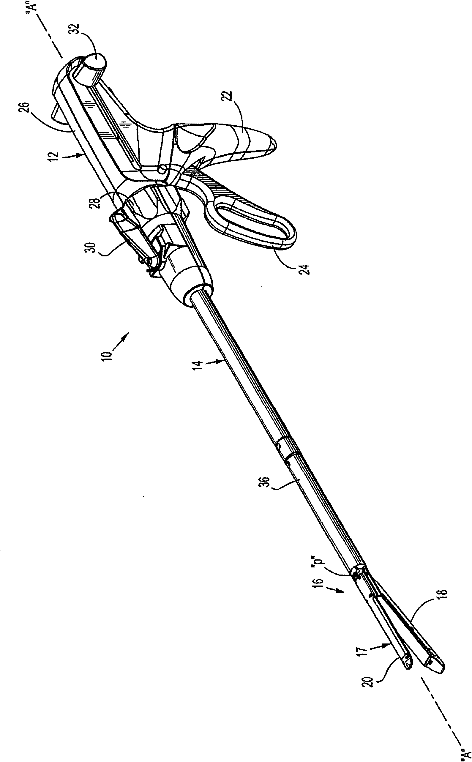
[0070] figure 1 A surgical device, generally designated 10, is shown, such as a surgical stapling device. For brevity, this disclosure will focus primarily on the tool assemblies of the surgical stapling device 10 described. A detailed discussion of other components of surgical stapling device 10 and methods of use is disclosed in US Patent No. 6,241,139, the disclosure of which is incorporated herein by reference.

[0071] The surgical anastomotic devi...


PUM

PropertyMeasurementUnit
lengthaaaaaaaaaa

Abstract

A loading unit for use with a surgical stapling apparatus is provided and includes a tool assembly having a cartridge assembly and an anvil assembly that are movable in relation to one another; a surgical buttress releasably secured to a tissue contacting surface of the anvil assembly and / or the cartridge assembly, wherein each surgical buttress is secured to the anvil assembly and / or the cartridge assembly by at least one anchor; a release assembly associated with the anvil assembly and / or the cartridge assembly; and a drive assembly slidably translatable through the tool assembly between proximal and distal positions, wherein the drive assembly actuates the release assembly to thereby release the anchor to free the surgical buttress from the anvil assembly and / or the cartridge assembly.

Description

technical field [0001] The present disclosure relates to a surgical device including a butress material. In particular, the present disclosure relates to a surgical anastomotic device including a detachable surgical buttress, and / or an endoscopic surgical anastomotic device including a detachable surgical buttress. Background technique [0002] Surgical devices for grasping or clamping tissue between opposed jaw structures and then joining the tissue with surgical fasteners are well known in the art. In some instruments blades are provided for cutting tissue that has been joined by fasteners. Fasteners are usually in the form of surgical staples, but two-piece polymeric fasteners are also available. [0003] Instruments used for this purpose may include two elongated jaw members for grasping or clamping tissue, respectively. In some surgical staplers, one of the jaw members has a staple magazine loaded with a plurality of staples arranged in at least two horizontal rows, ...

Claims


Application Information

Patent Timeline
Patent Type & Authority Applications(China)
IPC IPC(8): A61B17/072A61B17/94
CPCA61B17/07207A61B17/07292A61B17/068A61B2017/07214A61B2017/07271Y10T29/49826
Inventor 李·奥尔森厄尼·阿兰依帕特里克·莫泽尔兹
Owner TYCO HEALTHCARE GRP LP
Why Eureka
Try Eureka