Adaptive beam forming side lobe shaping method

An adaptive beam and side lobe technology, applied in the field of target detection, to achieve the effect of easy promotion, convenient upgrade, and avoidance of calculation

Inactive Publication Date: 2010-12-15
PLA AIR FORCE RADAR COLLEGE
View PDF4 Cites 7 Cited by
  • Summary
  • Abstract
  • Description
  • Claims
  • Application Information

AI Technical Summary

Problems solved by technology

[0005] The purpose of the present invention is to solve the difficulties and problems faced by the adaptive beamforming technology, and overcome the shortcomings and deficiencies of the prior art

Method used


Image

  • Adaptive beam forming side lobe shaping method
  • Adaptive beam forming side lobe shaping method
  • Adaptive beam forming side lobe shaping method

Examples


Embodiment Construction

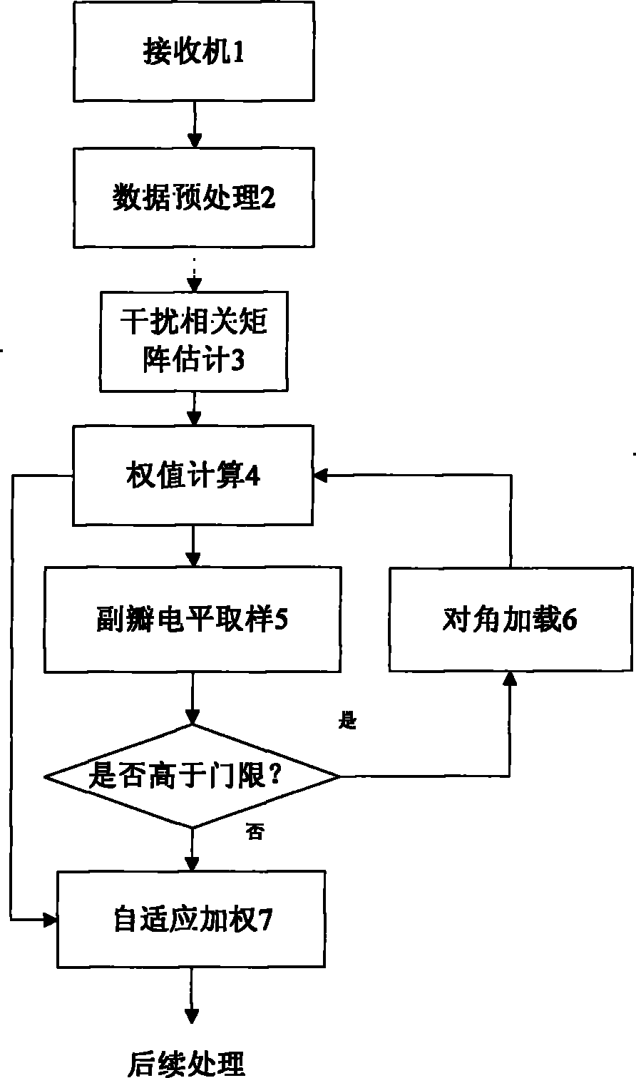
[0025] The principle of implementing the present invention is as follows: adaptive beamforming technology utilizes the feature of adjustable array antenna pattern to suppress interference, and its ultimate purpose is to realize effective detection of targets. However, when the interference has the same spatial information as the target, adaptive beamforming can only suppress the interference but fail to preserve the target. In fact, in this situation where the basis for countering jamming from the airspace is no longer available, other anti-jamming means should be adopted. Therefore, it is necessary to establish a corresponding "exit" mechanism to avoid the impact of adaptive beamforming on subsequent processing.

[0026] By diagonal loading, adaptive beamforming can be degenerated into conventional beamforming. The size of the diagonal loading determines the degree of degradation. The actual situation is complex and changeable. The ideal diagonal loading should make the bea...


PUM


Abstract

The invention discloses an adaptive beam forming side lobe shaping method. According to the method, a normalized adaptive directional diagram expected side lobe level magnitude is taken as a target, the magnitude of load amount of required diagonal load is obtained by iterative operation and reversal, an adaptive directional diagram is shaped by using the diagonal load, and the finally obtained directional diagram accords with the expected adaptive weight, wherein the specific steps are seen in attached diagrams. Compared with the prior art, the technique can load the load amount as low as possible by adjusting the magnitude of the diagonal load amount according to different conditions on the premise of ensuring that the directional diagram is not distorted so as to keep the inhibiting depth of the adaptive method on the interference; and the method is simple, and does not need complex deduction and fussy operation. The technique is not limited in radar equipment, can be widely applied to various antennas adopting arrays, has an electronic subsystem with interference suppression demand, and has popularization and application values.

Description

technical field [0001] The invention relates to an adaptive beamforming anti-jamming method in the field of radar signal processing, which is applicable to various signal processing systems using array antenna radar equipment, and can be used for target detection in the presence of various directional interference backgrounds. At the same time, the core theory and method can also be applied to other array signal processing systems that require interference suppression. Background technique [0002] Aiming at the difference in incident angle between the target signal and the interference signal, the adaptive beamforming technology uses the characteristics of the adjustable beam shape of the array antenna to adaptively adjust the zero point, the main lobe and other waveform resources to achieve the purpose of suppressing interference and retaining the signal. Disturbance of directional characteristics is effective. It has a wide range of applications in radar, sonar, communic...

Claims


Application Information

Patent Timeline
Patent Type & Authority Applications(China)
IPC IPC(8): G01S7/32G01S13/00
Inventor 陈建文鲍拯王永良王俊吴志文
Owner PLA AIR FORCE RADAR COLLEGE
Why Eureka
Try Eureka