Supercharge Your Innovation With Domain-Expert AI Agents!

Electric shaver

A razor and base technology, applied in metal processing and other directions, can solve problems such as reduced stiffness, inconvenient movement, and larger shearing edge units.

Active Publication Date: 2010-12-22
PANASONIC CORP
View PDF1 Cites 2 Cited by
  • Summary
  • Abstract
  • Description
  • Claims
  • Application Information

AI Technical Summary

Problems solved by technology

Therefore, when the trimmer unit is arranged at the upper end position, since the trimmer unit is only fixed below the main body, the rigidity in the front-rear direction of the main body portion of the trimmer unit may decrease especially during trimming.
[0005] In addition, with regard to the cutting blade unit described in Japanese Patent Application Laid-Open No. 2007-534394, since the attachment unit itself is attached to the main body, there is a problem that the cutting blade unit becomes large and inconvenient to move.

Method used


Image

  • Electric shaver
  • Electric shaver
  • Electric shaver

Examples


Embodiment Construction

[0021] Hereinafter, specific embodiments to which the present invention is applied will be described in detail with reference to the accompanying drawings.

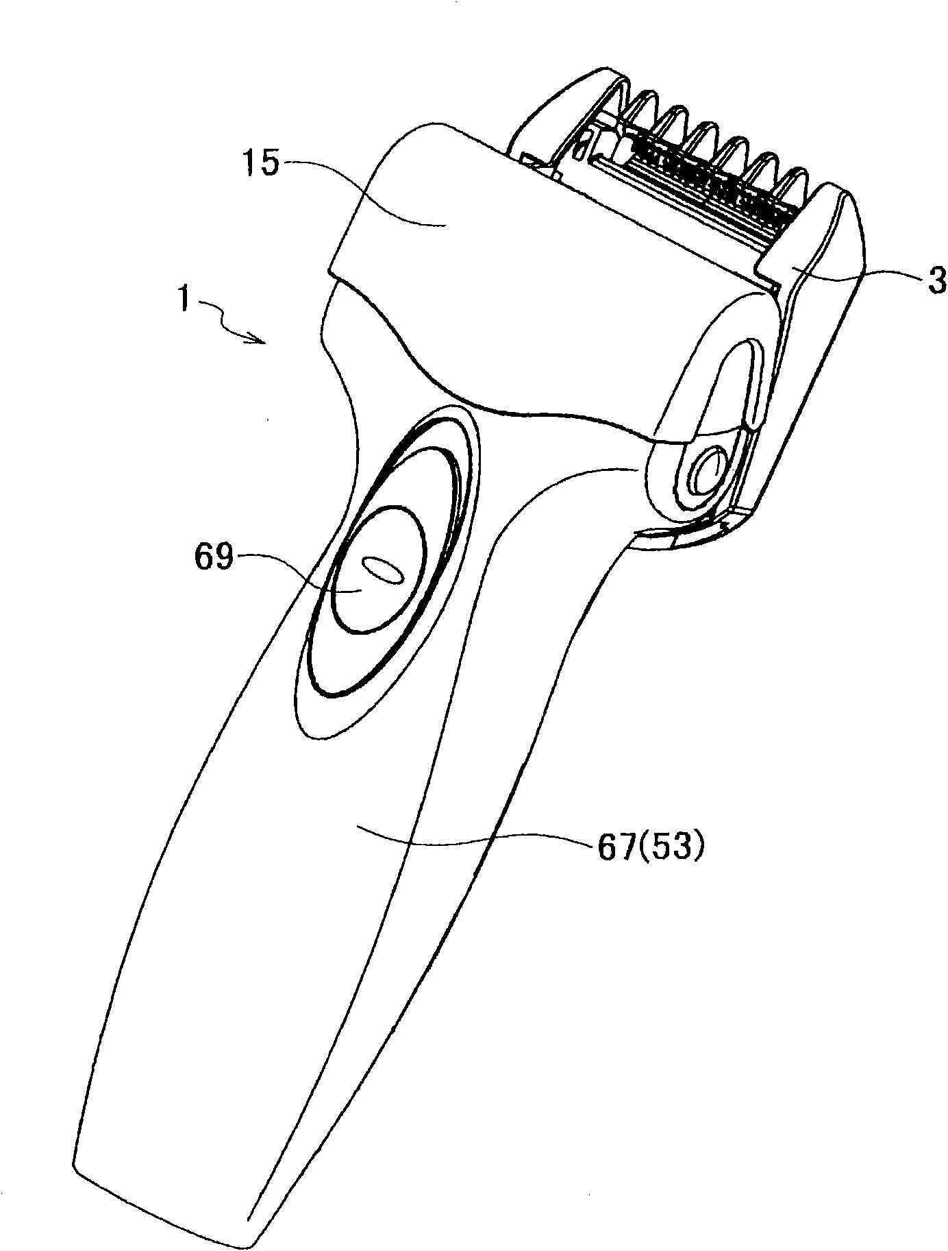
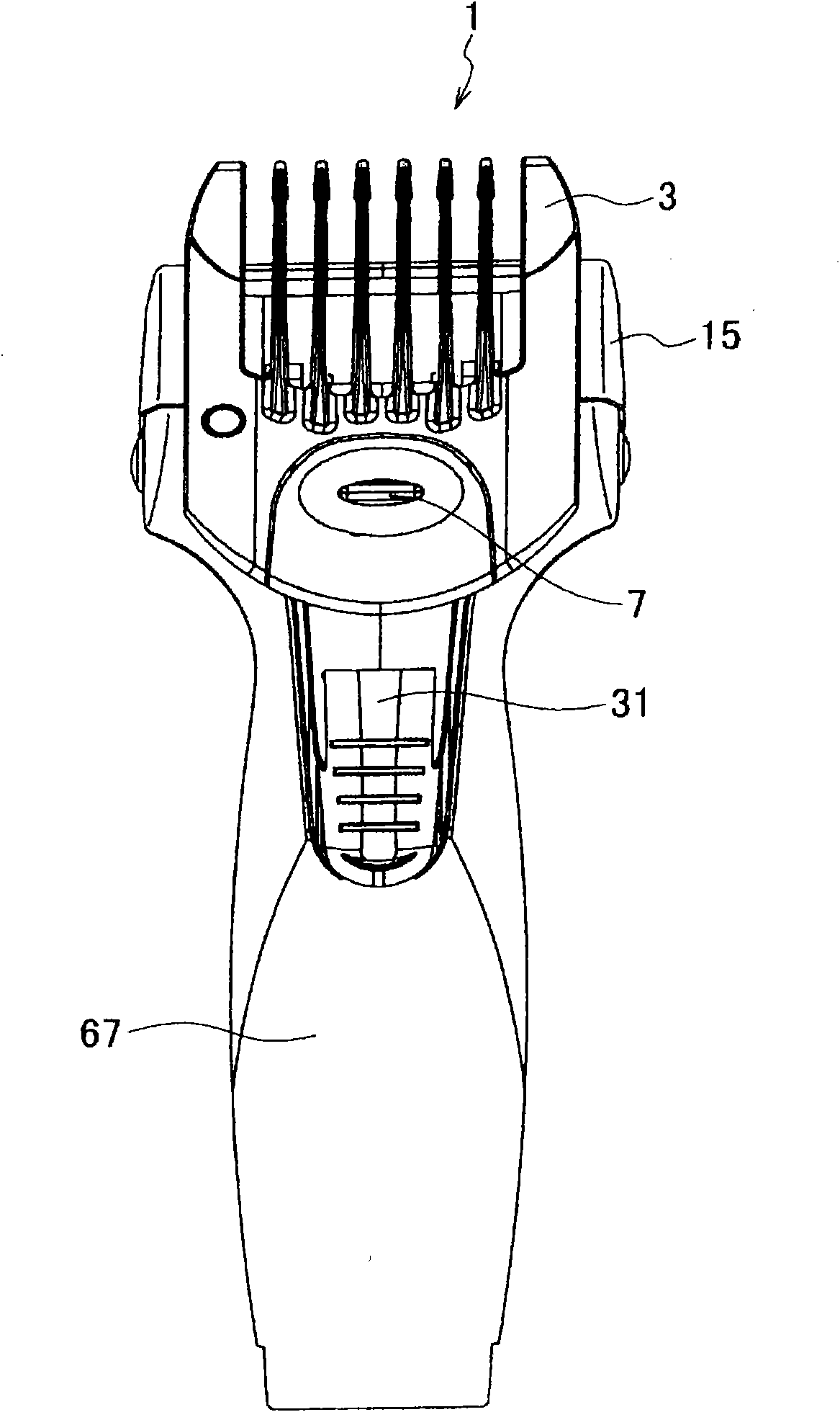
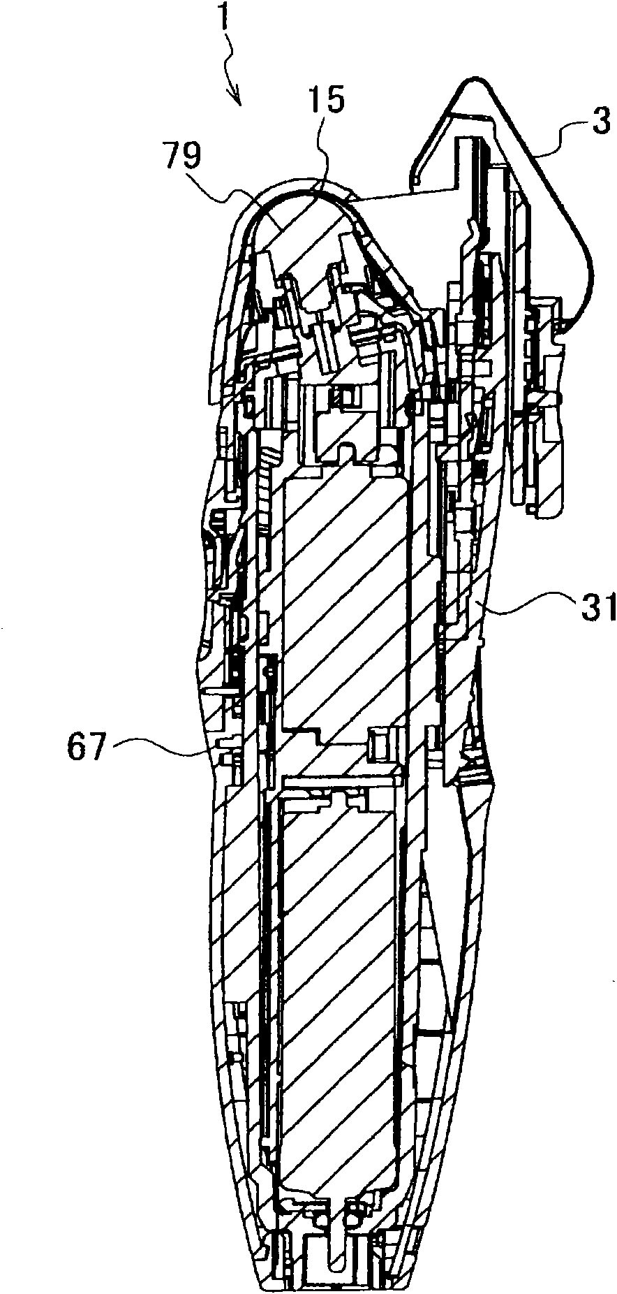
[0022] figure 1 It is a perspective view of the electric shaver according to the embodiment of the present invention viewed from the front side, figure 2 Yes figure 1 main view, image 3 Yes figure 2 longitudinal section view.

[0023] As shown in these drawings, the electric shaver 1 according to the embodiment of the present invention includes an electric shaver body 67 having a blade portion 79 arranged at an upper end portion thereof, and a cover body that covers the upper portion of the electric shaver body 67 on the front side from the upper portion of the front side of the electric shaver body 67 The base 15 , the attachment 3 attached to the back side of the cover base 15 , and the trimmer unit 31 slidably attached to the electric shaver main body 67 . A substantially circular switch 69 is disposed on the f...


PUM


Abstract

An electric shaver comprises a razor body having a blade part, a cap base attached to the razor body, and an attachment mounted to the cap base. The attachment is so constituted as to be capable of sliding on and detaching from the cap base.

Description

technical field [0001] The present invention relates to an electric shaver. Background technique [0002] Electric shavers in which an attachment is slidably formed in a trimmer unit have been known from the past. An example of such an electric shaver is disclosed in Japanese Patent Laid-Open Publication (Japanese Patent Application Laid-Open No. 2007-534394). This electric shaver can use only the main blade even when the attachment is attached. [0003] In addition, Japanese Patent Laid-Open Publication (JP 2007-534394 ) discloses a cutting blade unit (eg, an electric shaver) in which an attachment unit is attached to a main body. With this cutting unit blade unit, the trimmer is slidably arranged in the attachment unit. [0004] However, in the electric shaver described in Japanese Patent Laid-Open No. 2007-534394, the attachment is attached to the trimmer unit. Therefore, when the trimmer unit is arranged at the upper end position, since the trimmer unit is fixed only...

Claims


Application Information

Patent Timeline
Patent Type & Authority Applications(China)
IPC IPC(8): B26B19/38B26B19/10B26B19/20B26B19/42
CPCB26B19/3853B26B19/20B26B19/102B26B19/3813
Inventor 谷口文朗曾根大助高冈洋一
Owner PANASONIC CORP
Features
  • R&D
  • Intellectual Property
  • Life Sciences
  • Materials
  • Tech Scout
  • Unparalleled Data Quality
  • Higher Quality Content
  • 60% Fewer Hallucinations
Learn More