Brake safety device for crane

A technology of safety devices and cranes, which is applied in the direction of safety devices, transportation and packaging, load hanging components, etc., and can solve problems such as inconvenient operation

Inactive Publication Date: 2011-01-12
刘文富
View PDF0 Cites 4 Cited by
  • Summary
  • Abstract
  • Description
  • Claims
  • Application Information

AI Technical Summary

Problems solved by technology

[0003] The above scheme has the following disadvantages: when pulling the operating lever, it is necessary to overcome the relatively large force brought by the reset device, and the operation is relatively inconvenient

Method used


Image

  • Brake safety device for crane
  • Brake safety device for crane
  • Brake safety device for crane

Examples


Embodiment Construction

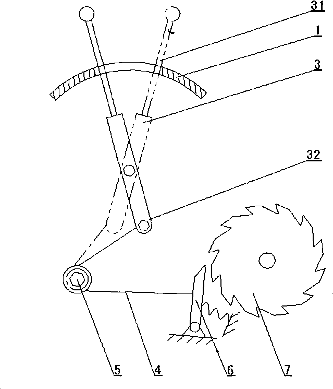
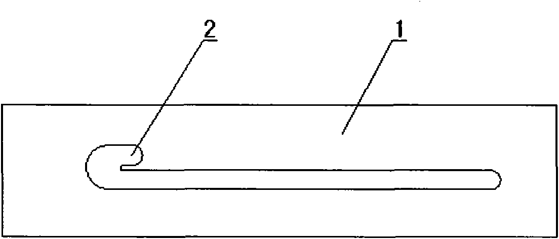
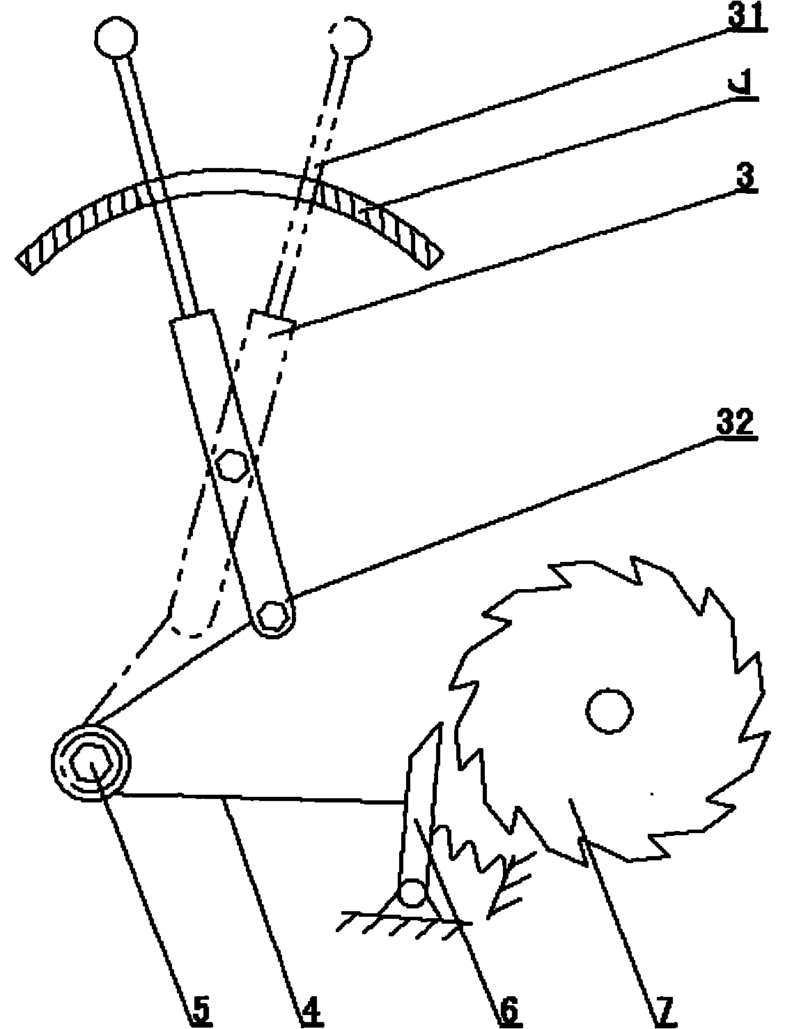
[0013] The specific structures and characteristics known in this solution will not be described here. Such as figure 1 As shown: there is a bar hole on the slot plate 1, the left end of the bar hole is provided with a stop groove 2, the operating rod 3 is a lever, and the power arm 31 of the operating rod 3 passes through the bar hole and can move therein , the resistance arm 32 of operating lever 3 is connected with traction rope 4, and power arm 31 is longer than resistance arm 32, and traction rope 4 is connected with ratchet 6 after fixed pulley 5 changes direction, and ratchet 6 is provided with reset spring, ratchet 6 cooperates with ratchet 7.

[0014] What has been described above is only a preferred embodiment of the present invention. It should be pointed out that for those skilled in the art, some modifications and improvements can be made without departing from the structure of the present invention, and these should also be regarded as the present invention. pro...


PUM


Abstract

The invention relates to a brake device for a hoisting device. The invention aims at providing a brake safety device for a crane, which is convenient to operate. The structure comprises an operating rod, a position-clamping slot plate, a traction rope, a pawl and a ratchet. A slot is arranged on the position-clamping slot plate, a stop slot is formed at one end of the slot, the operating rod is shaped like a lever, a power arm of the operating rod penetrates the slot and can move in the slot, a resistance arm of the operating rod is connected with the pawl through the traction rope, the power arm is larger than the resistance arm, and a reset device is arranged on the pawl for driving the pawl to be meshed with the ratchet. The technical scheme is characterized in that the adoption of the effort-saving lever mechanism is more convenient to operate.

Description

technical field [0001] The invention relates to a braking device for lifting equipment. Background technique [0002] A typical crane brake safety device includes: operating rod, support plate, steel rope, pawl and ratchet, the steel rope connects the operating rod and the ratchet, the ratchet is provided with a reset device, and the ratchet and the ratchet are engaged in the usual insurance state , to prevent the ratchet from rolling in a certain direction. The ratchet is associated with the lifting mechanism of the crane. When the ratchet is locked, the lifting mechanism is also locked accordingly. In the safe state, the heavy objects lifted by the crane can be prevented from accidentally falling. When it is necessary to release the safety state, the operating rod is pulled to drive the ratchet to avoid the ratchet wheel through the steel rope, and the operating rod is stuck on the support plate to maintain the non-safety state. [0003] The above solution has the followi...

Claims


Application Information

Patent Timeline
Patent Type & Authority Applications(China)
IPC IPC(8): B66C15/00
Inventor 黄书凯马光辉文怡然竺栋刘嘉陈家辉杨令
Owner 刘文富
Why Eureka
Try Eureka