
Circuit for pulse plasma thruster

A pulsed plasma and thruster technology, applied in the field of circuits, can solve problems such as inaccurate ignition control and complicated circuits, and achieve the effects of preventing damage caused by capacitors, controllable power conversion, and precise control of ignition frequency.

Inactive Publication Date: 2011-12-07
BEIHANG UNIV
View PDF0 Cites 1 Cited by
  • Summary
  • Abstract
  • Description
  • Claims
  • Application Information

AI Technical Summary

Problems solved by technology

The current research results include a high-voltage circuit using a counter-type switching converter. This circuit is relatively complicated and the ignition control is not accurate.

Method used


Image

  • Circuit for pulse plasma thruster
  • Circuit for pulse plasma thruster

Examples


Embodiment Construction

[0016] The present invention will be further described in detail below in conjunction with the accompanying drawings.

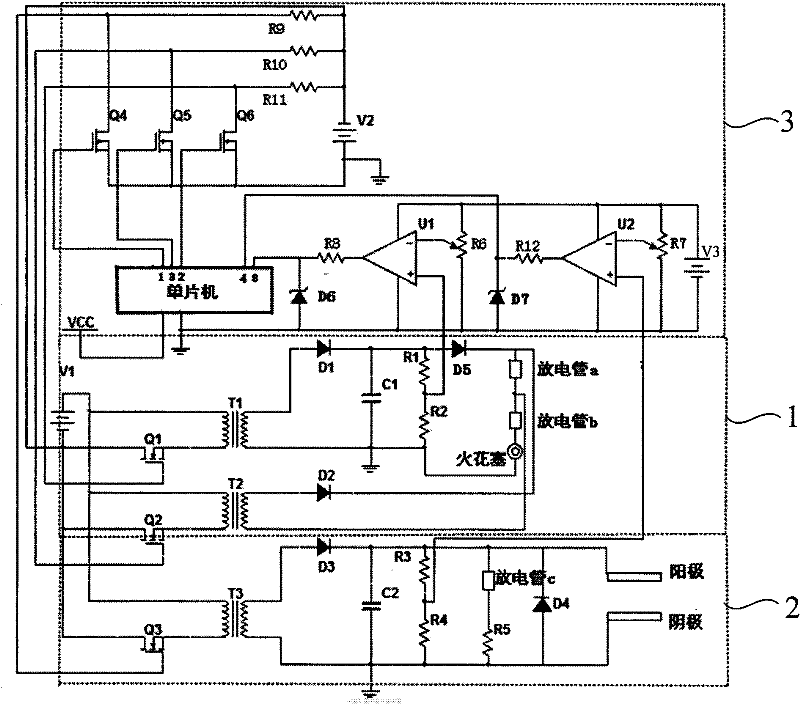
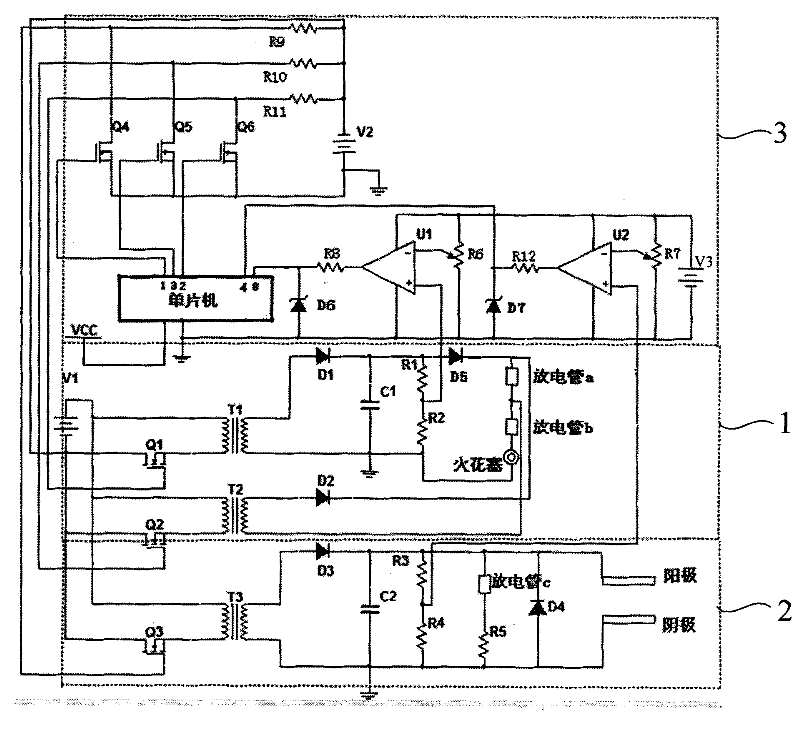
[0017] The present invention provides a kind of circuit that is used for pulse plasma thruster, mainly is made up of ignition circuit 1, energy storage circuit 2 and control circuit 3, as figure 1 shown.

[0018] The ignition circuit 1 is used to convert the satellite bus power supply V1 into a high-voltage pulse to charge the ignition capacitor C1, and discharge the spark plug after receiving the ignition signal.

[0019] The energy storage circuit 2 is used to convert the satellite bus power supply V1 into a high-voltage pulse to charge the energy storage capacitor C2.

[0020] The control circuit 3 is used to send a chopping signal for voltage conversion, monitor the voltages of the ignition capacitor C1 in the ignition circuit 1 and the energy storage capacitor C2 in the energy storage circuit 2 and send out an ignition signal.

[0021] The ignition cir...


PUM


Abstract

The invention discloses a circuit for a pulse plasma thruster, which comprises an ignition circuit, an energy storage circuit and a control circuit, wherein a singlechip in the control circuit outputs chopped wave signals; and pulse transformers in the ignition circuit and the energy storage circuit charge an ignition capacitor and an energy storage capacitor. When sampling voltages of the positive input ends of two voltage comparators reach a set ignition voltage and a set energy storage voltage respectively, the singlechip stops outputting the chopped wave signals, and after a set delay time, outputs ignition signals which generate trigger pulse high-tension electricity by the pulse transformer in the energy storage circuit, and then the pulse high-tension electricity is discharged to break gas discharge tubes down to produce electric spark to trigger ignition. The circuit has the advantage of realizing quick and controllable charge and accurate triggered ignition.

Description

technical field [0001] The technology belongs to the field of electric propulsion, relates to a circuit for a pulse plasma thruster, and specifically relates to circuit technologies such as automatic control. Background technique [0002] Micro-thrust engine technology for space such as electric propulsion is widely used in the aerospace field. Because the thruster for space applications requires high specific impulse and small mass, it brings great difficulties to the design of the thruster. The power processing unit of the pulse plasma thruster accounts for most of the mass of the thruster, and the performance of the thruster is also closely related to the characteristics of the circuit. The current research results include a high-voltage circuit using a counter-switching converter. This circuit is relatively complicated and the ignition control is not accurate. For details, see "Research on Performance of 40J Pulsed Plasma Thruster", Hu Zongsen, 2002.6. Contents of th...

Claims


Application Information

Patent Timeline
Patent Type & Authority Patents(China)
IPC IPC(8): F03H1/00H02J15/00
Inventor 卫强汤海滨王安良余鹏隋禄涛
Owner BEIHANG UNIV
Learn More