A high-voltage line distributed capacitance measuring device and its measuring method

A technology of distributed capacitance and high-voltage lines, which is applied to measuring devices, measuring electrical variables, measuring resistance/reactance/impedance, etc., can solve the problems of complex measurement methods, low safety factor, and difficult operation, and achieve high measurement accuracy and low investment cost. The effect of low cost and convenient wiring

Active Publication Date: 2016-04-13
西安兴汇电力科技有限公司
View PDF9 Cites 0 Cited by
  • Summary
  • Abstract
  • Description
  • Claims
  • Application Information

AI Technical Summary

Problems solved by technology

Nowadays, many capacitive current measurement methods are used, and the additional capacitance method and the metal grounding method are usually used for measurement. However, in actual use, the former measurement method is complicated and difficult to operate; the latter is dangerous and has a low safety factor.
In summary, there is a lack of a high-voltage line distributed capacitance measuring device and its measurement method with simple structure, reasonable design, simple measurement method, and accurate measurement results, which can measure the distributed capacitance of high-voltage lines in a charged state, and the measurement process is safe and reliable.

Method used


Image

  • A high-voltage line distributed capacitance measuring device and its measuring method
  • A high-voltage line distributed capacitance measuring device and its measuring method
  • A high-voltage line distributed capacitance measuring device and its measuring method

Examples


Embodiment Construction

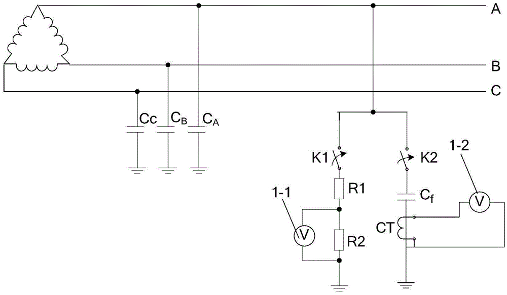
[0039] Such as figure 1 A high-voltage line distributed capacitance measurement device shown includes a phase voltage measurement circuit for measuring the phase voltage of the phase line to be tested and based on the bias capacitance C f ground capacitive current measurement circuit. The phase voltage measurement circuit is connected to the phase line to be tested. The ground capacitive current measurement circuit includes a bias capacitor C f and for current through the bias capacitor C f The current is detected by the current sense unit, the bias capacitor C f It is a ground capacitor or a reactor formed by connecting multiple capacitors in series or in parallel. The bias capacitor C f One end of it is connected to the phase line under test and the other end is grounded. The tested phase line is the A-phase, B-phase or C-phase line of the tested high-voltage line.

[0040] During the actual wiring, the A-phase, B-phase or C-phase lines of the tested high-voltage line ...


PUM


Abstract

The invention discloses a high-voltage line distributed capacitance measurement device and a measurement method thereof. The measurement device includes a phase voltage measurement circuit for measuring the phase voltage of a phase line to be tested and a ground capacitance current measurement circuit based on a bias capacitance Cf; The voltage measurement circuit is connected to the phase line to be tested; the ground capacitance current measurement circuit includes a bias capacitor Cf and a current detection unit for detecting the current flowing through the bias capacitor Cf, one end of the bias capacitor Cf is connected to the phase line to be tested and Its other end is grounded; Its measuring method comprises the steps: 1. Line phase voltage measurement before the bias capacitor is connected; 2. Line phase voltage measurement after the bias capacitor is connected; Carry out measurement; 4. Calculation of distributed capacitance. The invention has the advantages of reasonable design, convenient wiring, simple measurement method and accurate measurement result, and can measure the distributed capacitance of the high-voltage line under the electrified state, and the measurement process is safe and reliable.

Description

technical field [0001] The invention belongs to the technical field of distributed capacitance measurement of high-voltage lines, and in particular relates to a high-voltage line distributed capacitance measurement device and a measurement method thereof. Background technique [0002] At present, in my country's 6kV ~ 10kV power distribution system, the neutral point is not grounded or grounded through the arc suppression coil. Among them, the significant advantage of the neutral point ungrounded method is that the system can continue to operate for a short time when single-phase ground faults frequently occur (accounting for more than 60%). However, due to the existence of the ground capacitance of the power distribution system, it may cause intermittent arc grounding, ferromagnetic resonance and other neutral point displacement overvoltages, and even accidents, which will lead to breakdown of the weak insulation links of the entire power distribution system and equipment f...

Claims


Application Information

Patent Timeline
Patent Type & Authority Patents(China)
IPC IPC(8): G01R27/26
Inventor 尹之仁刘佳
Owner 西安兴汇电力科技有限公司
Why Eureka
Try Eureka