Pipe bender

A pipe bending machine and frame technology, applied in the field of pipe bending machines, can solve the problems of large investment and difficult guarantee of product quality

Inactive Publication Date: 2011-01-19
HENAN KELONG GRP
View PDF0 Cites 4 Cited by
  • Summary
  • Abstract
  • Description
  • Claims
  • Application Information

AI Technical Summary

Problems solved by technology

[0002] The shape of the condenser tube in the refrigeration industry is relatively complicated. There are not only a variety of bends with different curvatures, but also a three-dimensional bent tube product. The bending of this kind of tube can be carried out on a CNC tube bending machine, but it requires a large investment. , but using simple bending tools, the product quality is not easy to guarantee

Method used


Image

  • Pipe bender
  • Pipe bender
  • Pipe bender

Examples


Embodiment Construction

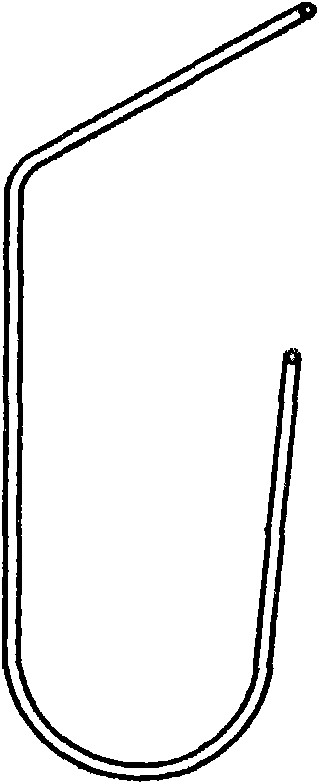
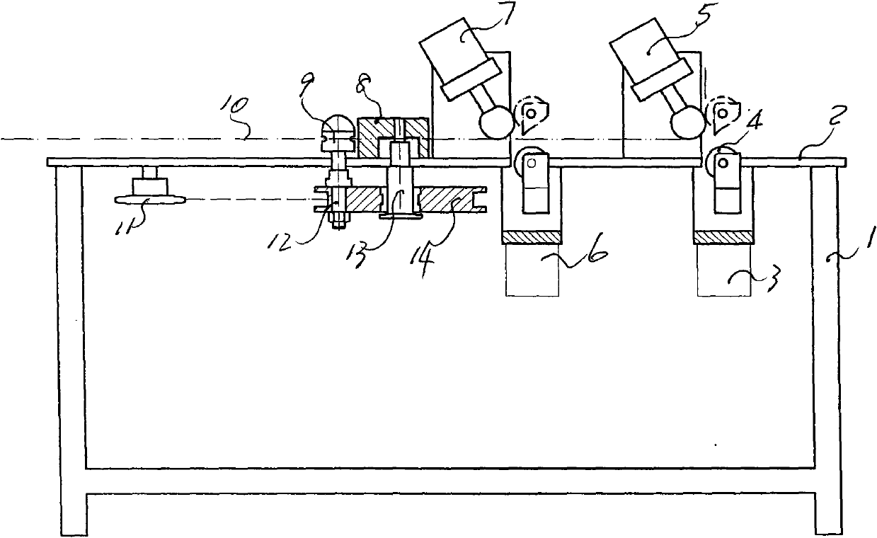
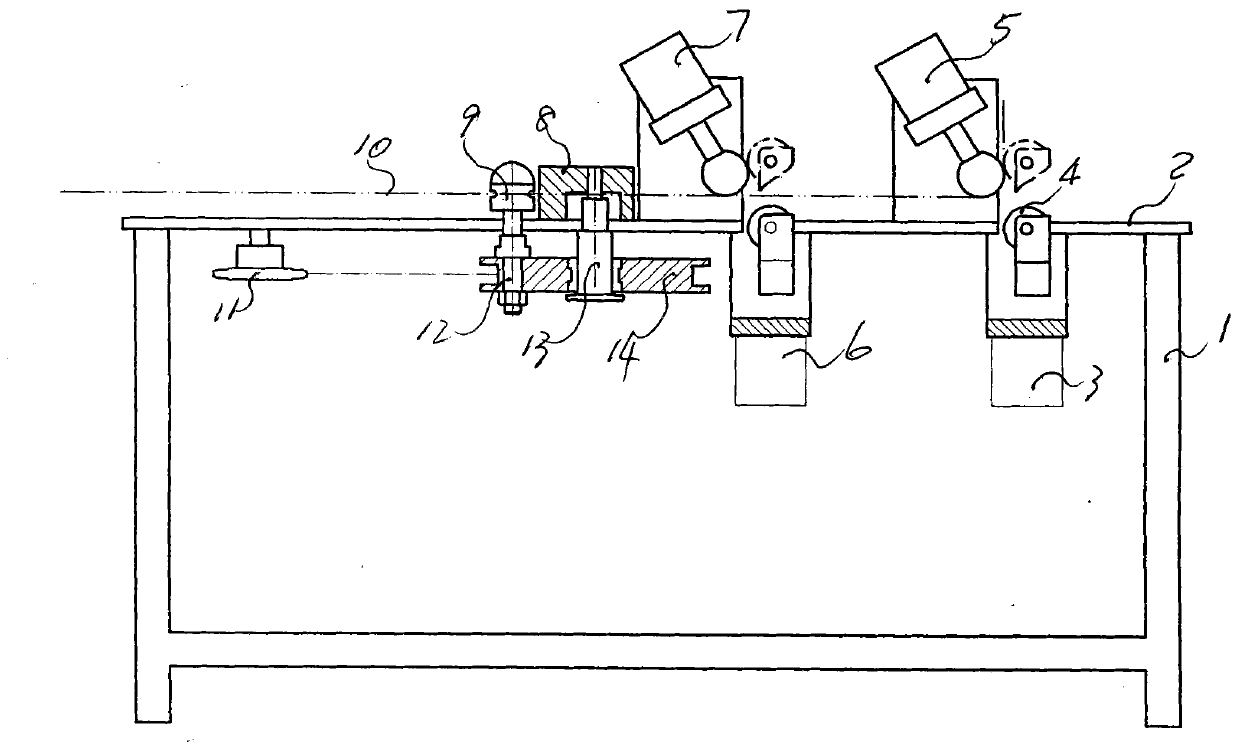
[0005] As a specific embodiment of the present invention, the above figure 1 , 2 It is a 120° bend and a 175° bend on the plane, and each of the two ends of the bend has a 90° bend perpendicular to the plane pipe. The pipe bender of the present invention can bend this pipe. There is a vertical first cylinder 3 under the platen 2 of the frame 1, and a roller 4 with an annular groove matching the bent pipe is arranged on its peripheral surface, and the roller is matched with the shaft on the piston rod of the cylinder 3, Above the platen opposite to this first cylinder 3 is provided with an inclined second cylinder 5, the piston end of this second cylinder has a rotating roller, the left outer edge of the roller on the piston rod of the first cylinder It is tangent to the outer edge of the right side of the roller on the piston rod of the second cylinder; a third cylinder 15 is arranged horizontally on the platen on the left side of the second cylinder, and the end of the pist...


PUM


Abstract

The invention discloses a pipe bender, relates to chipless machining of pipes and aims to design the pipe bender having low cost and high product quality. The key point of the technical scheme for realizing the aims is that: the pipe bender comprises a machine frame and a roller, wherein the bedplate of the machine frame is provided with a straight bending cylinder, a horizontal bending cylinder, a clamping cylinder, a U-shaped bending cylinder and a chain drive mechanism sequentially from the right side to the left side. The pipe bender is used for bending the pipes with plane bending and vertical bending.

Description

Technical field: [0001] The invention relates to a non-cutting processing of pipes, in particular to a pipe bending machine. Background technique: [0002] The shape of the condenser tube in the refrigeration industry is relatively complicated. There are not only a variety of bends with different curvatures, but also a three-dimensional bent tube product. The bending of this kind of tube can be carried out on a CNC tube bending machine, but it requires a large investment. , and the use of simple bending tools, product quality is not easy to guarantee. Invention content: [0003] The purpose of this invention is to design a pipe bender with low cost and good product quality. The technical solution of the present invention to realize the purpose of the invention is to include a frame and rollers, and it is characterized in that: the frame platen is provided with an inclined first cylinder, a horizontally arranged third cylinder, and a horizontally arranged first cylinder fr...

Claims


Application Information

Patent Timeline
Patent Type & Authority Applications(China)
IPC IPC(8): B21D7/04
Inventor 王在中李四清杨学清
Owner HENAN KELONG GRP
Why Eureka
Try Eureka