Slide disengaging structure

A technology of row position and row block, which is applied in the field of mold row design, and can solve problems such as slide block demoulding, undercut pull damage, undercut deformation, etc.

Inactive Publication Date: 2011-02-02
VANGUARD TECH WUXI
View PDF7 Cites 6 Cited by
  • Summary
  • Abstract
  • Description
  • Claims
  • Application Information

AI Technical Summary

Problems solved by technology

[0002] Because some products have undercuts on the side, they cannot be demolded with conventional sliders. ...

Method used


Image

  • Slide disengaging structure
  • Slide disengaging structure

Examples


Embodiment Construction

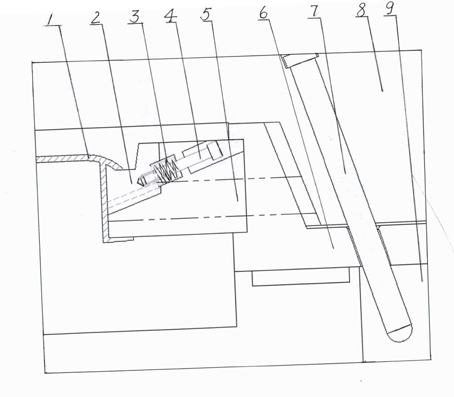
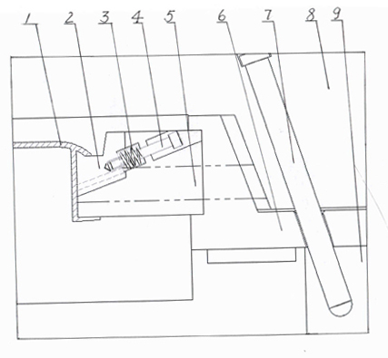
[0008] See figure 1 , the present invention comprises an upper mold 8, a lower mold 9, a row block 5 and an oblique guide column 7, the row block 5 is provided with a small row block 2 which is slidably connected to it, and the small row block 2 and the large row block 5 is connected by the compression spring and the shoulder bolt 4. When the mold is parted, the inclined guide column drives the large travel block 5 to move through the travel seat 6, and the small travel block 2 moves relatively downward along the slope under the action of the spring 3. The small row block 2 is separated from the undercut of the product 1, and after the large row block 5 moves a certain distance, the large row block 5 drives the small row block 2 to move together through the action of the shoulder bolt 4, realizing the undercut product. demoulding.


PUM


Abstract

The invention provides a slide disengaging structure, which can simply and conveniently de-mold a reversal fastener product as a slider and a reversal fastener can be de-molded at the same time to finish the de-molding of the reversal fastener product. The slide disengaging structure comprises an upper die, a lower die, a slide block and an inclined guide post, and is characterized in that: the slide block is provided with a small slide block connected with the slide block in a positioning and sliding way, and is in slant sliding connection with the small slide block; and the small slide block and the large slide block are connected with a shouldered tap bolt by a pressure spring.

Description

technical field [0001] The invention relates to the technical field of mold row position design, in particular to a row position release structure. Background technique [0002] Because some products have undercuts on the side, they cannot be demolded with conventional sliders. Forcibly dragging the mold will damage or deform the undercuts, which cannot meet the product quality requirements. Contents of the invention [0003] In view of the above problems, the present invention provides a row-position release structure, which can release the undercut at the same time when the slider is demoulding, thus completing the demoulding of the undercut product. [0004] Its technical solution is as follows: a positioning belt positioning mechanism, which includes an upper mold, a lower mold, a positioning block and an inclined guide column, and is characterized in that: the positioning block is provided with a small sliding connection with its positioning. A row position block, th...

Claims


Application Information

Patent Timeline
IPC IPC(8): B29C33/44
Inventor 张卫
Owner VANGUARD TECH WUXI
Why Eureka
Try Eureka