Tripping mechanism of permanent magnet circuit breaker, permanent magnet circuit breaker and switchgear

A technology of tripping mechanism and permanent magnet mechanism, which is applied in the direction of protection switch, parts of protection switch, operation/release mechanism of protection switch, etc., can solve problems such as unreliability and misoperation, and achieve reliable use and reduce misoperation Possibility, effect of improving safety

Active Publication Date: 2019-12-10
ZHEJIANG PEOPLE ELE APPLIANCE
View PDF1 Cites 0 Cited by
  • Summary
  • Abstract
  • Description
  • Claims
  • Application Information

AI Technical Summary

Problems solved by technology

[0006] Therefore, the technical problem to be solved by the present invention is to overcome the problem that the external tripping mechanism of the permanent magnet circuit breaker in the prior art is prone to misoperation and not reliable enough, so as to provide a more reliable permanent magnet circuit breaker. Tripping mechanism of type circuit breaker, permanent magnet circuit breaker and switchgear

Method used


Image

  • Tripping mechanism of permanent magnet circuit breaker, permanent magnet circuit breaker and switchgear
  • Tripping mechanism of permanent magnet circuit breaker, permanent magnet circuit breaker and switchgear
  • Tripping mechanism of permanent magnet circuit breaker, permanent magnet circuit breaker and switchgear

Examples


Embodiment 1

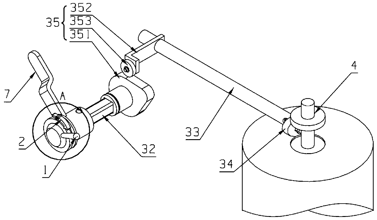
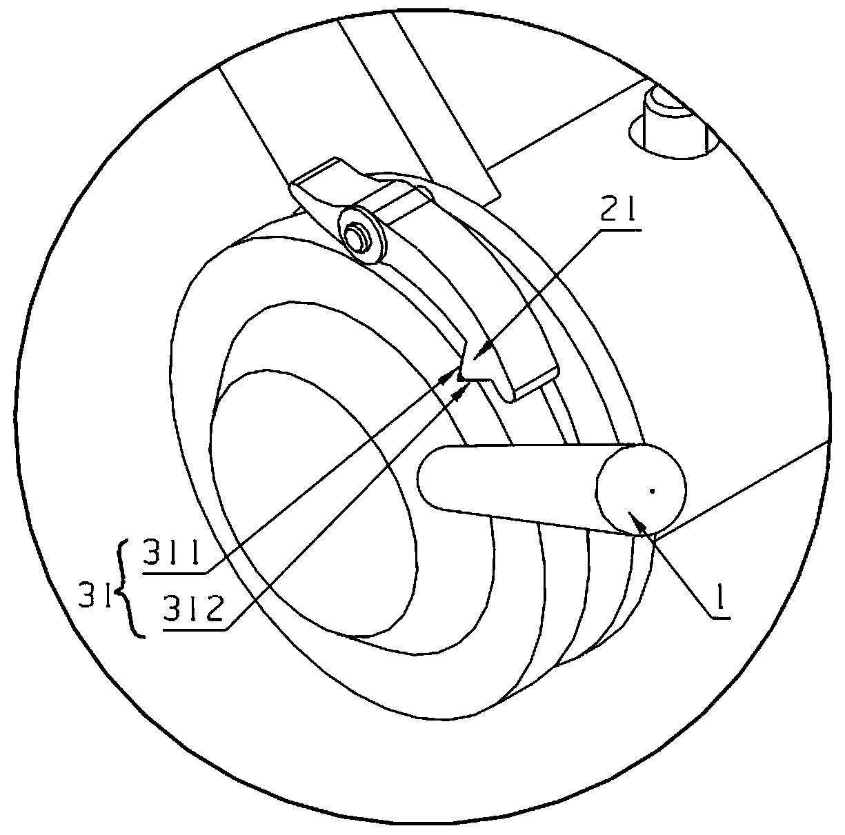
[0050] Such as figure 1 and figure 2 Shown is Embodiment 1 of the present invention. This embodiment provides a tripping mechanism for a permanent magnet circuit breaker, which includes a handle 1 arranged outside the circuit breaker housing 6, and also includes a linkage structure 3, movable parts 2 and The biasing part, the linkage structure 3 is installed on the circuit breaker housing 6, one end is linked with the handle 1, and the other end can drive the moving armature 4 of the permanent magnet mechanism under the drive of the handle 1 to break away from the switch. position; the movable part 2 can abut against the linkage structure 3 so that the handle 1 cannot drive the linkage structure 3 to move; the biasing force of the biasing member makes the movable part 2 and the linkage structure 3 maintain the abutment state. Specifically, the biasing part is specifically a torsion spring, and the movable part 2 is specifically an S-shaped lock plate. The middle part of the...

Embodiment 2

[0066] Such as image 3 Shown is Embodiment 2 of the present invention. This embodiment provides a permanent magnet circuit breaker, which is equipped with the tripping mechanism of the permanent magnet circuit breaker described in the above embodiment. The tripping mechanism of the permanent magnet circuit breaker described in Example 1 therefore has the technical effect of the above-mentioned Embodiment 1.

Embodiment 3

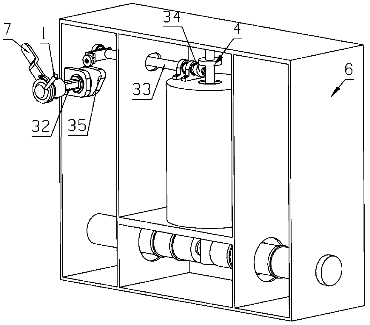
[0068] Such as Figure 4 and Figure 5 Shown is Embodiment 3 of the present invention. This embodiment provides a switchgear equipped with the tripping mechanism of the permanent magnet circuit breaker described in Embodiment 1, and the handle 1 is arranged in the switchgear Outside the cabinet body 5. Since the tripping mechanism of the permanent magnet circuit breaker described in the first embodiment is installed in this embodiment, it also has the technical effect of the first embodiment above.


PUM


Abstract

The invention discloses a tripping mechanism of a permanent magnet circuit breaker and belongs to the circuit breaker field. The tripping mechanism comprises a handle, a linkage structure, a moving component and a bias pressure component, wherein the handle is arranged outside a shell of the circuit breaker; the linkage structure is installed on the circuit breaker, one end is linked with the handle and the other end is driven by the handle to drive a moving armature of a permanent magnetic mechanism to be separated from a closing position; the moving component abuts against the linkage structure so that the handle can not drive the linkage structure to move; and a bias force of the bias pressure component make the moving component and the linkage structure keep a contact state. In the invention, safety of the tripping mechanism during usage is increased and a tripping structure can be used reliably.

Description

technical field [0001] The invention relates to the field of circuit breakers, in particular to a tripping mechanism of a permanent magnet circuit breaker, a permanent magnet circuit breaker and a switch cabinet. Background technique [0002] A circuit breaker refers to a switching device that can close, carry and break current under normal circuit conditions and can close, carry and break current under abnormal circuit conditions within a specified time. The process of switching the circuit breaker from the closed state to the open state is called the tripping of the circuit breaker. In recent years, there has been a circuit breaker that uses the power of a permanent magnet to close and open the circuit breaker, which is called a permanent magnet circuit breaker. The permanent magnet circuit breaker is widely used because of its unique permanent magnet mechanism, small operating energy, no hidden danger of degaussing, long life, and strong anti-interference ability. In th...

Claims


Application Information

Patent Timeline
Patent Type & Authority Patents(China)
IPC IPC(8): H01H71/10
CPCH01H71/10H01H71/1018H01H71/1054
Inventor 卢伟胡振宇林继耀包续东
Owner ZHEJIANG PEOPLE ELE APPLIANCE
Why Eureka
Try Eureka