Stapler

A stapler and staple technology, applied in the direction of manufacturing tools, staple staple tools, etc., can solve problems such as wrong binding

Active Publication Date: 2011-02-02
利市爱珂品牌集团两合有限责任公司
View PDF0 Cites 0 Cited by
  • Summary
  • Abstract
  • Description
  • Claims
  • Application Information

AI Technical Summary

Problems solved by technology

Undesirable false bindings resulting from such staple deformation

Method used


Image

  • Stapler
  • Stapler
  • Stapler

Examples


Embodiment Construction

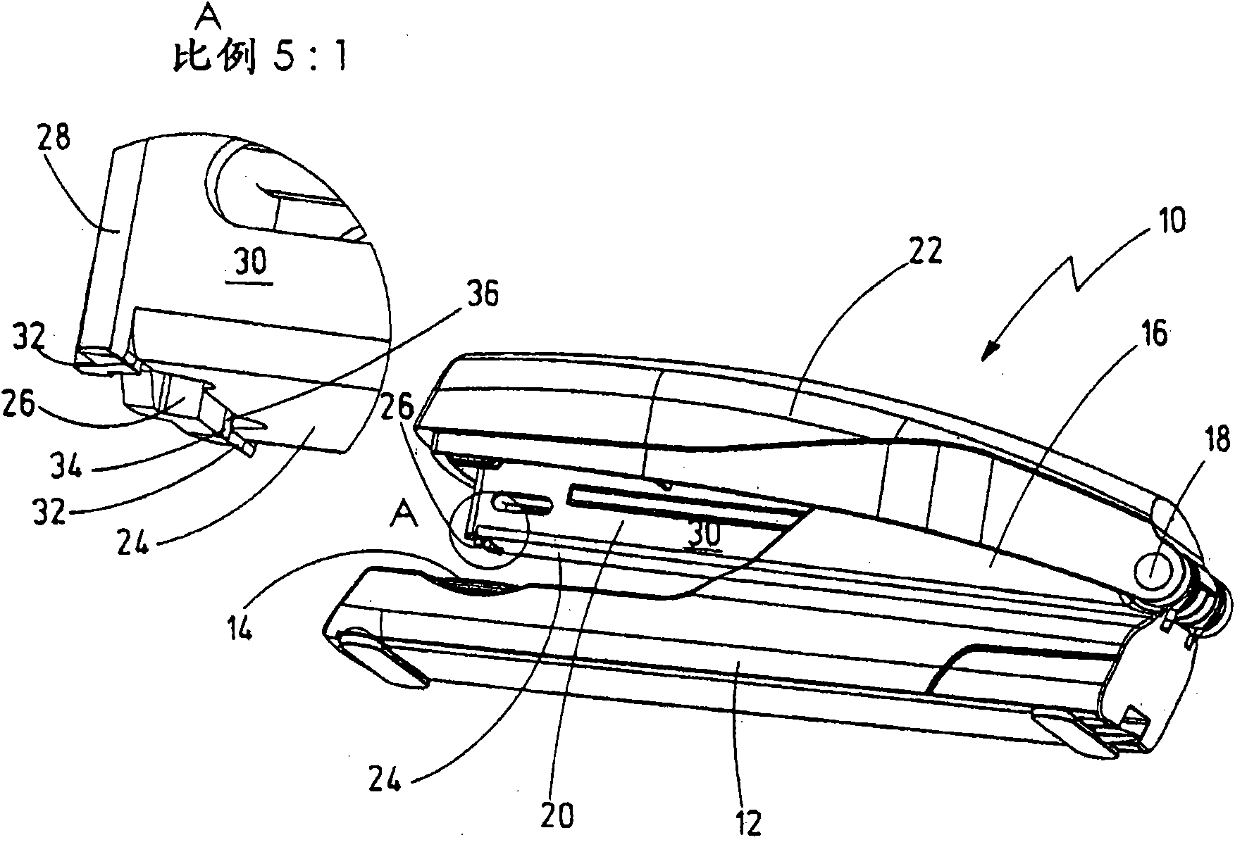
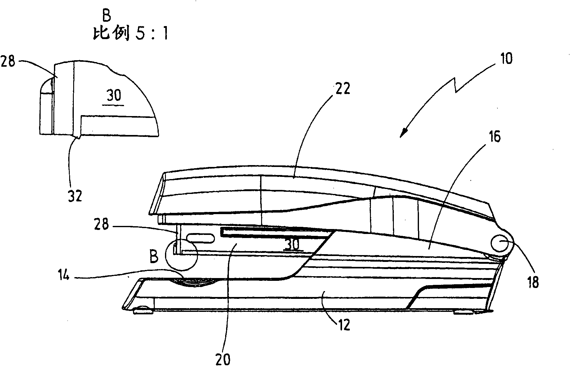
[0012] The stapler 10 shown in the figure has a bottom anvil arm 12 , in the front region of which, on its upper side, a bottom anvil 14 is arranged. In its rear area, the anvil arm 12 has a bearing seat 16 in which a transverse axis 18 is mounted, about which the nail magazine 20 can be pivoted in a limited manner relative to the anvil arm 12 . A driving arm 22 is pivotably supported in the bearing seat 16 around the transverse axis 18 relative to the anvil arm 12 and the nail magazine 20, the driving arm has a plastic cover used as a hand lever and a pair for receiving in the nail magazine 20. The staples exert force on the drive.

[0013] In order to guide the respective foremost staple received in the staple magazine 20 by means of an applied force by the driver, the staple magazine 20 has a staple delivery slot 26 in its bottom wall 24 . The staple output gap is delimited toward the front end of the magazine 20 by a stop plate 28 against which the frontmost staple is pre...


PUM


Abstract

The invention relates to a stapler (10) comprising: an anvil arm (12) which in its front region bears an anvil plate (14) on which documents can be placed,a staple magazine (20) which can be pivoted to a limited extent about a transverse pivot (18) on a bearing block (16) in the rearward region of the anvil arm (12),and a driver arm (22) which bears a driver for feeding the staples through a staple discharge slot (26) at the front end of the staple magazine (20) and which can be pivoted to a limited extent about the transverse pivot (18) with respect to the staple magazine (20) and the anvil arm (12), wherein the staple discharge slot (26) extends transversely through a bottom wall (24) of the staple magazine (20) between the magazine side walls (30) which run from the front end towards the bearing block (16) and is bounded with respect to the magazine front end by a stop plate (28) for the staples. According to the invention, the staple discharge slot (26) is closed with respect to the side walls (30) of the staple magazine (20), the staple magazine (20) is provided on each of its side walls (30) with a prong (32) which projects from the bottom wall (24), and the prongs (32) are arranged on both sides of the staple discharge slot (26).

Description

technical field [0001] The invention relates to a stapler according to the preamble of claim 1 . Background technique [0002] This stapler is used to bind multi-page documents together with staples. For this purpose, a string of staples is accommodated in the magazine, which string is pressed spring-supported against a stop plate. Towards the front end of the magazine, the stop plate defines a staple delivery slot through which the respective frontmost staple is guided by the driver by applying force when pressing down on the drive arm and the bottom anvil arm of the magazine gap. The staple penetrates the document with its arms and deforms in the deforming profile in the bottom anvil. The staple output slot extends transversely through the bottom wall of the staple magazine and has a width in that direction that is approximately equal to the width of the staple as measured from one staple arm to the other. The staple delivery slots not only extend laterally on the bott...

Claims


Application Information

Patent Timeline
Patent Type & Authority Applications(China)
IPC IPC(8): B25C5/02
CPCB25C5/025
Inventor T·施奈德U·施奈德K·洛伊特
Owner 利市爱珂品牌集团两合有限责任公司
Why Eureka
Try Eureka