Pin tray dental prostheses modeling system with re-usable tray

a technology of dental prostheses and trays, which is applied in the field of pin tray dental prostheses modeling systems with reusable trays, can solve the problems that the exterior surfaces of the prosthesis cannot simply replicate the surface of the die segment, and achieve the effects of facilitating the placement of the pinned die segment within the trays, minimizing the number of different type parts, and quick and easy removal

Inactive Publication Date: 2005-07-05
HONSTEIN JERRY P
View PDF1 Cites 22 Cited by
  • Summary
  • Abstract
  • Description
  • Claims
  • Application Information

AI Technical Summary

Benefits of technology

[0023]A preferred embodiment of a pin tray modeling system according to the present invention includes an opposing tray for making a casting of a dental impression which was made of teeth opposed to those which are to be fitted with prostheses. The preferred embodiment also includes components which hingedly couple a master tray holding a master impression cast to an opposing tray holding an opposing impression cast and forming therewith an articulator mechanism which enables the occlusal surfaces of the master and opposing casts to be brought into pivotable contact with one another, thereby simulating closure of a patient's jaws and proper occlusion of the teeth modeled in the two casts. If dental prostheses are required only for one jaw, the cast made of the opposing jaw does not have to have removable die segments. Therefore, the opposing tray need not be provided with the previously described structural features which enable die segments to be removed and replaced within the tray. However, to minimize the number of different type parts required by the present system, the opposing tray may be constructed identically to the master tray, even though the frangible base and indexing grooves and ribs are not required for the opposing cast, since it may remain permanently affixed to the tray.
[0024]In any event, both the master and opposing trays, which may be of identical construction, are provided with a hinge coupler bracket which extends longitudinally outwards from a short end of each tray. The bracket has the shape of a bifurcated L-bracket including a flat longitudinally disposed horizontal floor plate which extends perpendicularly outwards from a short vertical end wall of the tray. The floor plate of the bracket has a flat horizontally disposed upper surface which is recessed slightly below the upper surface of the perimeter edge wall of the tray. A pair of rectangularly-shaped connector plates protrudes upwardly from an outer longitudinal end portion of the floor plate. The outer connector plates from a pair of trays are releasably joined together by a hinge coupler member that has an upper piano-type hinge, and opposed horizontal upper support plates located on opposite sides of a horizontally disposed hinge pin. The hinge coupler has protruding perpendicularly downwardly from outer ends of each support plate a vertical connector plate which has at the lower end thereof a pair of inwardly facing C-shaped channel members which have therein opposed vertically disposed C-shaped channels adapted to insertably receive an outer upstanding end plate of a tray coupler. This construction enables the outer slotted ends of the hinge coupler to be readily slipped removably over the upstanding connector flange plates of a longitudinally aligned pair of trays, i.e., a master tray and an opposing tray, and thereby hingedly coupling the two trays together so that upper surfaces of the trays may be pivoted towards and away from one another to simulate closure and opening of a patient's jaws.

Problems solved by technology

In general, the exterior surfaces of the prosthesis cannot simply replicate those of the die segments.

Method used


Image

  • Pin tray dental prostheses modeling system with re-usable tray
  • Pin tray dental prostheses modeling system with re-usable tray
  • Pin tray dental prostheses modeling system with re-usable tray

Examples


Embodiment Construction

A. Drawing Description Summary

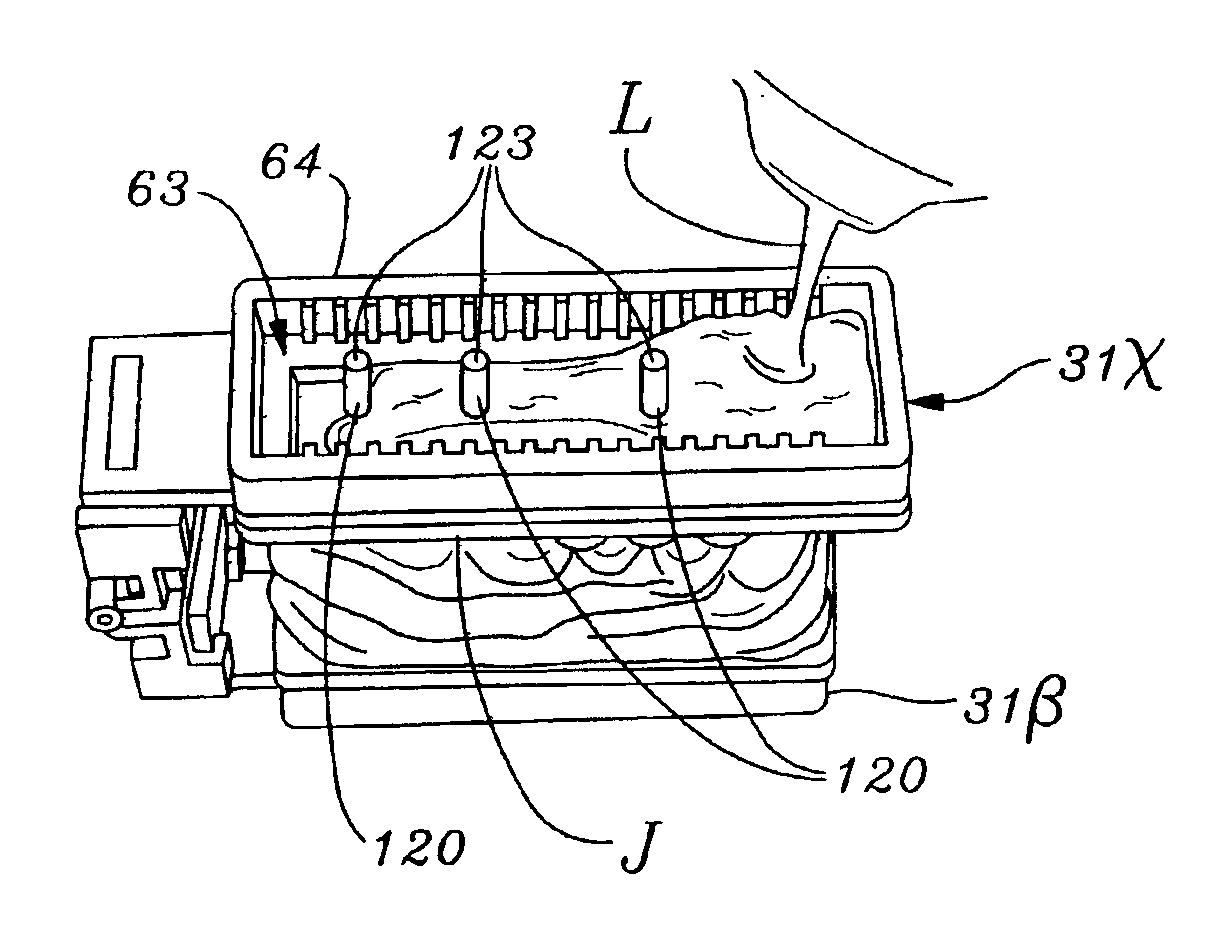
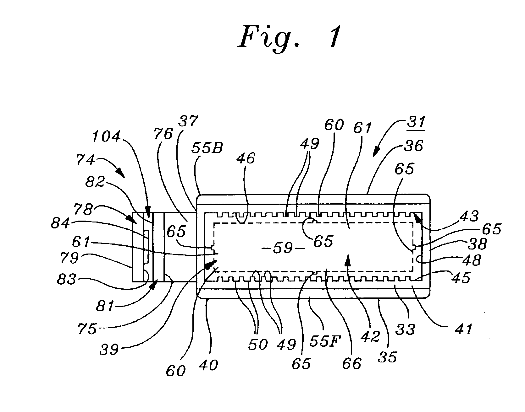
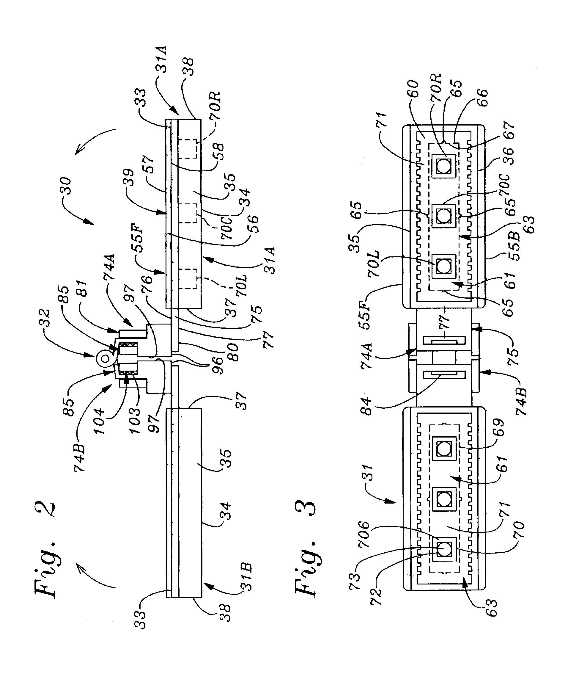
[0070]FIGS. 1-3 and 19-21 illustrate components of a basic embodiment of dental prostheses modeling system according to the present invention, while FIG. 22 illustrates a drilling alignment fixture for use in an alternate embodiment of the system.

[0071]FIGS. 4-8 illustrate steps in a method of making a dental model cast from a single quadrant impression for use in fabricating dental prostheses, according to a basic embodiment of the invention.

[0072]FIGS. 9-11 illustrate preliminary steps in making master and opposing dental model casts from master and opposing mold impressions made by teeth in upper and lower jaws of a patient, use a “double-bite” or “triple” impression tray.

[0073]FIGS. 12-15 illustrate further steps in the method of fabricating a dental prostheses model according to the present invention, from either a single-bite or double-bite impression.

[0074]FIGS. 16-18 illustrate a finished pair of dental prostheses model casts mounted in an artic...


PUM


Abstract

A dental prostheses modeling system includes a re-usable tray having in an upper part thereof a trough for receiving a semi-liquid casting material such as plaster of Paris or die stone, the trough having opposed vertical walls in which are formed alternating vertically disposed ribs and grooves for molding complementary shaped grooves and ribs in opposed sides of the base of a dental model casting molded in said tray. The trough has a base frame which overlies an upwardly concave lower cavity for receiving liquid die stone after the casting base has solidified, hardened and been removed. The base frame has therethrough an elongated aperture joining the upper trough to the lower cavity. A resilient insert is removably lodged in the base frame aperture to form therewith a liquid-tight seal, whereupon liquid die stone is poured into the upper trough to form the base of a dental model casting. After the casting has hardened, the insert is removed, and pins are fitted into selected portions of the cast base. The tray is then inverted to receive liquid die stone which hardens to form a stone base matrix for insertably receiving pins protruding from the casting base. The casting is then severed into segments which are releasably re-engageable along with adjacent portions of the casting within the tray, proper registration between segments of the casting being effected by insertable receipt of pins within holes formed in the matrix during hardening thereof, and engagement between ribs and grooves of the casting segment bases with complementarily-shaped grooves and ribs in the inner side walls of the upper tray trough.

Description

RELATED APPLICATION INFORMATION[0001]The present application is a continuation-in-part application of application Ser. No. 10 / 376,375, filed Feb. 26, 2003.BACKGROUND OF THE INVENTION[0002]A. Field of the Invention[0003]The present invention relates to articles and methods used in the fabrication of dental prostheses such as crowns and bridges made of various combinations of metal and ceramic materials and used to overlie or replace imperfect or missing teeth. More particularly, the invention relates to a system for use in fabricating crowns and bridges, the system including an apparatus and method for making from a mold or impression of a patient's teeth a dental model cast which is formed from solidified liquid die stone poured into the mold and an upper portion of a tray. The dental model cast is segmentable into die segments, each of which has both horizontally protruding ribs and grooves for releasably engagement with complementary-shaped grooves and ribs formed in the tray, and...

Claims


Application Information

Patent Timeline
Patent Type & Authority Patents(United States)
IPC IPC(8): A61C9/00A61C11/00A61C11/02
CPCA61C9/002A61C11/02
Inventor HONSTEIN, JERRY P.BARNES, RICHARDSIRAGUSA, ANTHONY
Owner HONSTEIN JERRY P
Why Eureka
Try Eureka