Power generation assemblies

A technology for generating sets and generating sets, which is applied to wind turbine components, wind turbine combinations, engines, etc., and can solve problems such as the severe tipping of the enlarged TLP device and the severe tipping of the VFF device

Inactive Publication Date: 2011-02-02
OCEAN WIND TECH
View PDF2 Cites 17 Cited by
  • Summary
  • Abstract
  • Description
  • Claims
  • Application Information

AI Technical Summary

Problems solved by technology

[0006] These TLPs can be built to be more robust than VFF units of the same height, but as referenced below Figure 13 to Figure 15 As discussed in detail, they are more likely than VFF units to tip over significantly under large horizontal forces, and this susceptibility to horizontal forces causes problems in the ins

Method used


Image

  • Power generation assemblies
  • Power generation assemblies
  • Power generation assemblies

Examples


Embodiment Construction

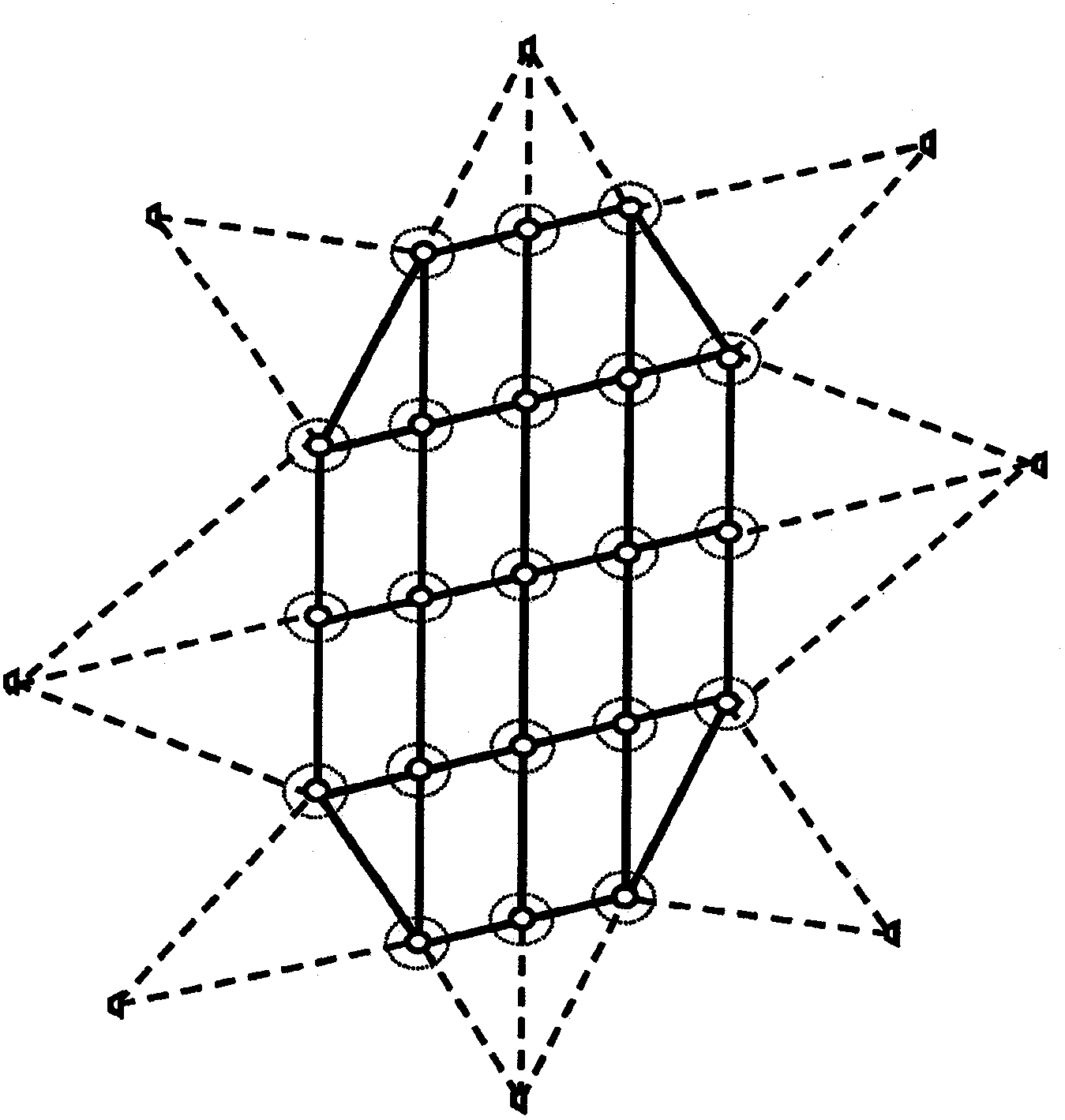
[0039] As already indicated, a first aspect of the present invention concerns improvements to the generator sets and wind farms described in the aforementioned WO 2005 / 040604, wherein some or all of the flotation devices are in the form of tension leg platforms. Accordingly, the TLP unit of the present invention may comprise any of the optional features of the flotation device described in WO 2005 / 040604.

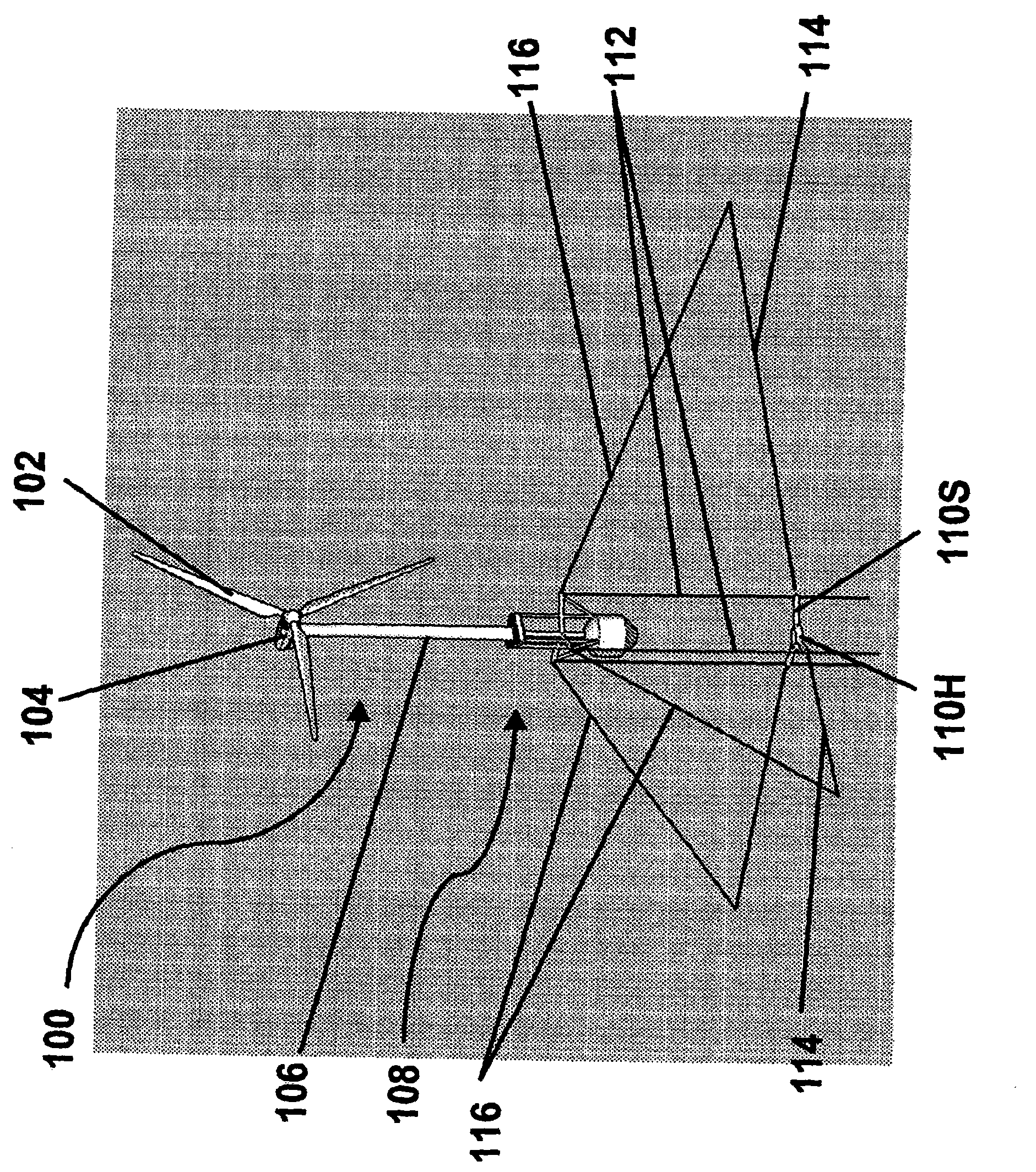
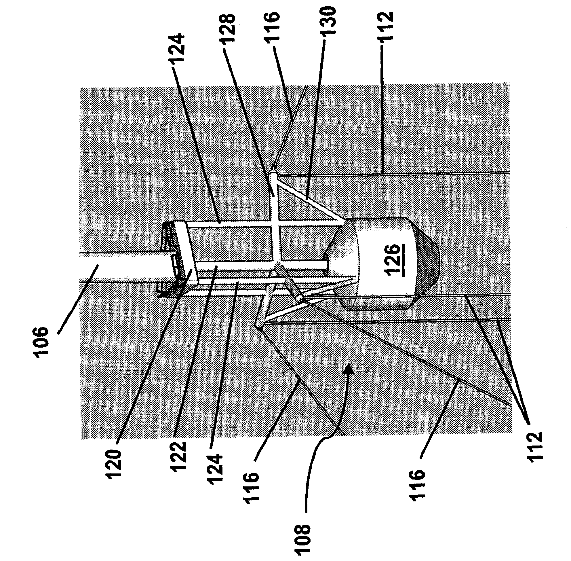
[0040] in these drawings figure 1 is a schematic perspective view from above of the front to one side of a tension leg platform assembly (generally designated 100 ) which may be used in the TLP train of the present invention. Apparatus 100 includes a wind rotor 102 comprising a plurality of blades (three shown) and mounted on a hub (or nacelle) 104, rotatable about a horizontal axis sufficiently high above the water's surface so that the rotor blades are Rotate without contacting the water surface; in fact, to ensure that the full velocity of the wind is utilized by the r...


PUM


Abstract

A floating power generation assembly has at least three floating units provided with power generation means and floating in a body of water. At least one of the three floating units is a tension leg platform. The assembly also comprises first anchors secured to a surface beneath the water, and first cables connecting the buoyant body to the first anchors. Second anchors are secured to the underwater surface and connected by second cables to the floating units. The floating units are arranged substantially at the vertices of at least one triangle or quadrilateral.

Description

technical field [0001] The present invention is related to International Patent Application Publication No. WO 2005 / 040604. [0002] The invention relates to generator sets and equipment for use therewith. In particular, the present invention relates to (a) a water generating set; and (b) a method of placing a flotation device on water. Background technique [0003] The aforementioned WO 2005 / 040604 discusses the advantages of wind-driven generators, in particular the ability to install wind farms (ie wind-driven generator collection systems) in deep water without the need for rigid structures on the seabed or other underwater solid surfaces The advantages. The above-mentioned application describes a floating power generating unit having, as components, at least three flotation devices floating on a body of water and at least three anchors fixed to submerged solid surfaces, each flotation device being provided with a power generating device, each The anchors are connected...

Claims


Application Information

Patent Timeline
IPC IPC(8): F03D9/00
CPCE02B2017/0091F03D11/045Y02E10/725Y02E10/38F05B2240/93F05B2240/96F03D9/005Y02E10/72Y02E10/727F05B2210/18F05B2240/95F03D1/001B63B21/502B63B35/44B63B2035/446F03D13/22F03D13/25F03D13/10F03D9/257Y02E10/30
Inventor S·山本W·E·小科尔伯恩
Owner OCEAN WIND TECH
Why Eureka
Try Eureka