
Coupling assembly

A technology of coupling and guide, applied in the direction of connecting member, connection, thin plate connection, etc., can solve problems such as difficult installation

Inactive Publication Date: 2011-02-09
HERMAN MILLER INC
View PDF0 Cites 0 Cited by
  • Summary
  • Abstract
  • Description
  • Claims
  • Application Information

AI Technical Summary

Problems solved by technology

Installation can be difficult if the spacing between locations on one part does not exactly match the spacing between locations on the other part

Method used


Image

  • Coupling assembly
  • Coupling assembly
  • Coupling assembly

Examples


Embodiment Construction

[0020] The invention is described with reference to the drawings, wherein like elements are indicated by like numerals. The relationship and function of the various elements of the invention are better understood from the following detailed description. However, the embodiments of the present invention described below are merely examples, and the present invention is not limited to the embodiments shown in the drawings.

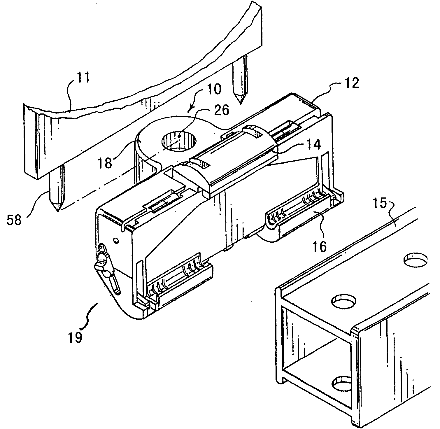
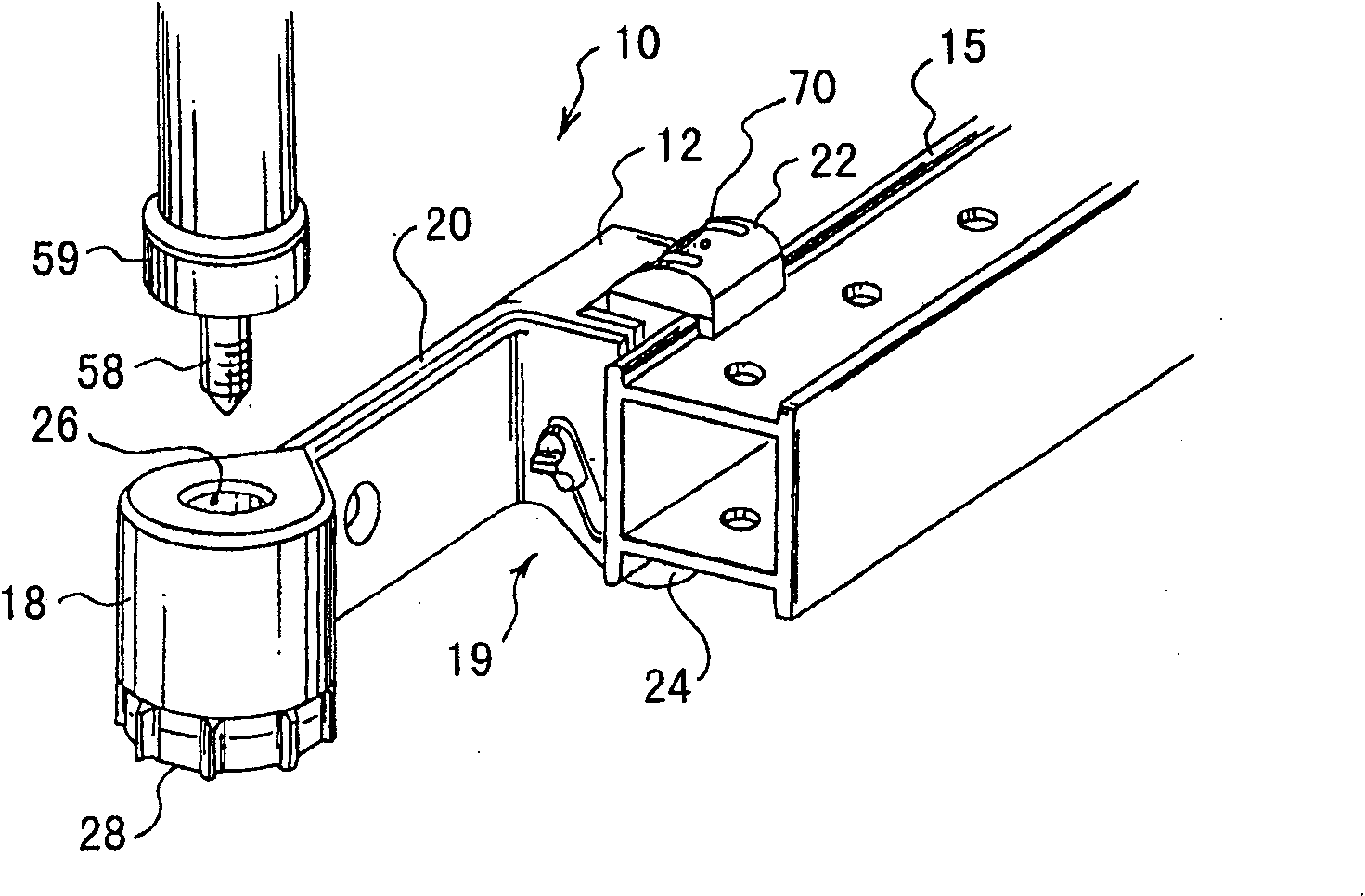
[0021] The present invention provides a support system 10, one embodiment of which is shown in figure 1 middle. The support system 10 is configured to connect together one or more workspace system components, such as mounting a screen 11, storage, electronics, universal implement rack, etc., to a work surface such as a desk structure 15 or frame. Typically, a component (such as the screen 11) has two or more spaced connection locations (in one embodiment , configured as a pair of downwardly extending rods 58). It should be understood that a "component" is...


PUM


Abstract

A connection system including a self-adjusting mount for coupling various furniture components together. The connection system can aid in coupling furniture components together with differing manufacturing tolerances. The self-adjusting mount is adapted to receive a connecting member and is capable of simultaneously moving in a first and second directions to couple with the connecting member. The self-adjusting mount may also secure the connecting member, thereby fixing the location of the connecting member.

Description

[0001] Cross References to Related Applications [0002] This application claims the benefit of US Provisional Application No. 61 / 020,600, filed January 11, 2008, the entire contents of which are hereby incorporated by reference. technical field [0003] The present invention relates to an assembly for joining together two or more parts and, in particular, to a connecting system for joining together various furniture parts. Background technique [0004] Often, furniture components and other workspace systems are shipped unassembled and then assembled at the job site, or disassembled at one location, moved, and assembled at another location. Additionally, additional furniture components are sometimes added or removed to modify an existing workspace system. [0005] Although furniture components and other workspace systems are manufactured to be compatible with each other, installation can be difficult when manufacturing tolerances differ between where the different component...

Claims


Application Information

Patent Timeline
Patent Type & Authority Applications(China)
IPC IPC(8): F16B5/02
CPCF16B5/025F16B21/06F16B5/0225Y10T403/5741Y10T403/76Y10T403/7005
Inventor T·J·麦克利恩
Owner HERMAN MILLER INC
Learn More