Supercharge Your Innovation With Domain-Expert AI Agents!

Automatic adjustment guide device

A guiding device and automatic adjustment technology, which is applied in the direction of building types, buildings, towers, etc., and can solve the problems of inability to achieve automatic adjustment and detachment

Active Publication Date: 2012-07-04
ATLAS COPCO (NANJING) CONSTR & MINING EQUIP CO LTD
View PDF6 Cites 0 Cited by
  • Summary
  • Abstract
  • Description
  • Claims
  • Application Information

AI Technical Summary

Problems solved by technology

For example, when the roller 1 hits a high point or a low point on the guide 2, since the traditional guide device cannot be automatically adjusted, the contact between the roller 1 and the guide 2 will be disengaged

Method used


Image

  • Automatic adjustment guide device
  • Automatic adjustment guide device
  • Automatic adjustment guide device

Examples


Embodiment Construction

[0015] The present invention will be described in further detail below with reference to the accompanying drawings.

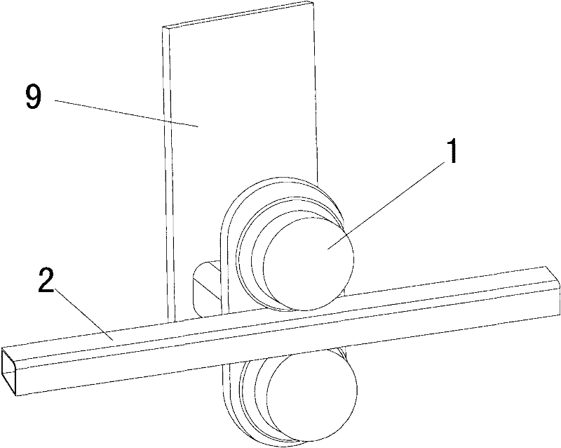
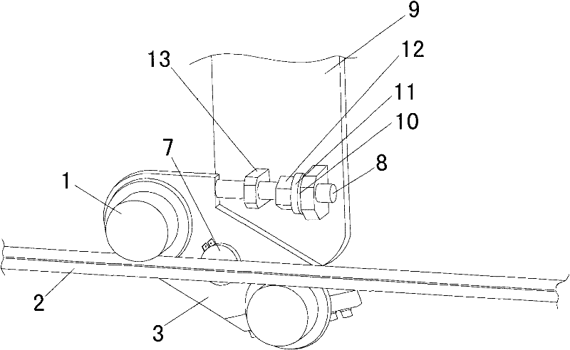
[0016] In a first embodiment of the self-adjusting guide according to the present invention, as figure 2 As shown, it includes a first mounting plate 9, a guide rail 2 and a guide mechanism connected with the first mounting plate 9 and moving along the guide rail 2. The guide mechanism includes a second mounting plate 3 and two rollers arranged on the second mounting plate 3. A shaft 1, a guide rail 2 is placed between two rollers 1, a first mounting plate 9 is provided with a pivot shaft 7 perpendicular to the first mounting plate 9, and the second mounting plate 3 is pivotally connected to the The first mounting plate 9; the two rollers 1 are mounted on the second mounting plate 3, the second mounting plate 3 is supported by the rollers 1, and the setting of the rollers 1 enables the second mounting plate 3 to rotate freely. The two rollers 1 are arranged a...


PUM


Abstract

The invention provides an automatic adjustment guide device. The guide device comprises a first mounting plate, a guide rail and a guide mechanism which is connected with the first mounting plate and moves along the guide rail, wherein the guide mechanism comprises a second mounting plate and two rolling shafts which are arranged on the second mounting plate; the guide rail is arranged between the two rolling shafts; a pivotal axis vertical to the first mounting plate is arranged on the first mounting plate; the second mounting plate can be pivotally connected to the first mounting plate by the pivotal axis; the two rolling shafts are arranged on the second mounting plate in a direction which forms a certain angle with a length direction of the guide plate and are tightly stuck to the guide rail by pivoting the second mounting plate; and an adjustment mechanism which is used for pivoting the guide mechanism is arranged on the first mounting plate so as to ensure that the two rolling shafts are tightly stuck to the guide rail. The automatic adjustment guide device of the invention can automatically and accurately realize a guide function and can ensure that the rolling shafts contact a guide part under various conditions.

Description

technical field [0001] The invention relates to a guide device, in particular to an automatic adjustment guide device. Background technique [0002] like figure 1 As shown, the conventional guide device comprises two rollers 1 arranged vertically along the guide 2 at a fixed distance. Since the vertical distance between the two rollers 1 is fixed, the contact between the rollers 1 and the guide member 2 is restricted by the manufacturing tolerance of the guide member 2 . If the straightness of the guide member 2 along the length direction changes, the contact between the roller 1 and the guide member 2 along the length direction of the guide member 2 cannot be maintained. For example, when the roller 1 hits a high point or a low point on the guide member 2, the contact between the roller 1 and the guide member 2 will be disengaged because the conventional guide device cannot realize automatic adjustment. SUMMARY OF THE INVENTION [0003] The purpose of the present inven...

Claims


Application Information

Patent Timeline
Patent Type & Authority Patents(China)
IPC IPC(8): E04H12/18
Inventor 史蒂文·马
Owner ATLAS COPCO (NANJING) CONSTR & MINING EQUIP CO LTD
Features
  • R&D
  • Intellectual Property
  • Life Sciences
  • Materials
  • Tech Scout
  • Unparalleled Data Quality
  • Higher Quality Content
  • 60% Fewer Hallucinations
Learn More