Supercharge Your Innovation With Domain-Expert AI Agents!

Method of machine tool calibration

A technology for machine tools and rotating parts, used in milling lathes, calibration lathes such as lathes, and can solve problems such as unacceptable time consumption

Active Publication Date: 2011-02-16
RENISHAW PLC
View PDF2 Cites 1 Cited by
  • Summary
  • Abstract
  • Description
  • Claims
  • Application Information

AI Technical Summary

Problems solved by technology

However, it is not always possible to perform tentative cuts on the workpiece, and the time-consuming process can be unacceptably time-consuming

Method used


Image

  • Method of machine tool calibration
  • Method of machine tool calibration
  • Method of machine tool calibration

Examples


Embodiment Construction

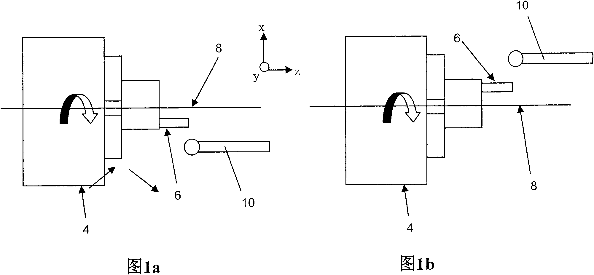
[0083] Referring to FIG. 1 , a plan view of a lathe chuck 4 is shown, with features 6 . Feature 6 may be an integral feature formed in or on the chuck or may be formed in a part held by the chuck. Also shown is an associated measurement probe 10, such as a touch trigger probe of the kind described in EP0283486. Such probes are typically mountable on a lathe (not shown) tool holder and are interchangeable with one or more cutting tools.

[0084] The chuck 4 is rotatable about an axis of rotation 8, commonly referred to as the lathe centerline or C-axis.

[0085] Figure 1a Illustrates the chuck 4 in a first orientation, while Figure 1b A second orientation is shown in which the chuck 4 is turned by 180° relative to the first orientation.

[0086] As mentioned above, the lathe centerline (ie, the axis of rotation of the chuck) must be accurately determined to ensure that the part can be accurately turned to the desired diameter. In order to determine precisely the axis of ...


PUM


Abstract

Methods are described for calibrating a turning machine (30) having a first rotatable portion or chuck (4;32;202) for holding a workpiece. The first rotatable portion (4;32;202) has a first feature (6;34;206) associated therewith. The method comprises the steps of using a measurement probe (10;38;204;236) to determine the position of the first feature (6;34;206), rotating the first rotatable portion (4;32;202) through an angle, and using said measurement probe (10;38;204;236) to determine the new position of the first feature(6;34;206). The extension of the technique to swivel head mill-turn machines (30) is also described.

Description

[0001] This patent application is a divisional application of the patent application with the application number 200680047062.1 (international application number PCT / GB2006 / 004643), the applicant is "Renish Howe Company", and the invention name is "machine tool calibration method". technical field [0002] The invention relates to machine tools and in particular to methods of calibrating lathes such as lathes, mill-turn machines and the like. Background technique [0003] Lathes are known. On a conventional lathe, the workpiece is held in a chuck and rotated at high speed. The cutting tool then contacts the rotating workpiece and cuts or "turns" the workpiece into the desired shape. [0004] Mill-turning machines, which can be considered as a variant of lathes, are also known. This lathe includes a rotating chuck to hold the workpiece and also has a device for rotating the cutting tool. The workpiece is then turned as on a standard lathe and / or features can be milled on t...

Claims


Application Information

Patent Timeline
Patent Type & Authority Applications(China)
IPC IPC(8): G05B19/401
CPCG05B2219/50029G05B2219/50139G05B2219/50022G05B2219/45136G05B19/401G05B2219/50032B23B3/06B23B25/06G05B2219/50152Y10T82/2502Y10T82/10
Inventor 保罗·马克斯特德马克·托马斯·伯克利·桑德斯戴维·罗伯茨·麦克默特里克里斯托弗·雷·沃森
Owner RENISHAW PLC
Features
  • R&D
  • Intellectual Property
  • Life Sciences
  • Materials
  • Tech Scout
  • Unparalleled Data Quality
  • Higher Quality Content
  • 60% Fewer Hallucinations
Learn More