Driving force control apparatus for vehicle and driving force control method for vehicle

A control device and driving force technology, which is applied to the layout of multiple different prime movers, power devices, control devices, etc.

Inactive Publication Date: 2011-02-23
TOYOTA JIDOSHA KK
View PDF7 Cites 0 Cited by
  • Summary
  • Abstract
  • Description
  • Claims
  • Application Information

AI Technical Summary

Problems solved by technology

When the alternator is used for applications other than securing power for these machines, there is a problem that the required power cannot be secured or the alternator may actively operate to cause overvoltage

Method used


Image

  • Driving force control apparatus for vehicle and driving force control method for vehicle
  • Driving force control apparatus for vehicle and driving force control method for vehicle
  • Driving force control apparatus for vehicle and driving force control method for vehicle

Examples


Embodiment Construction

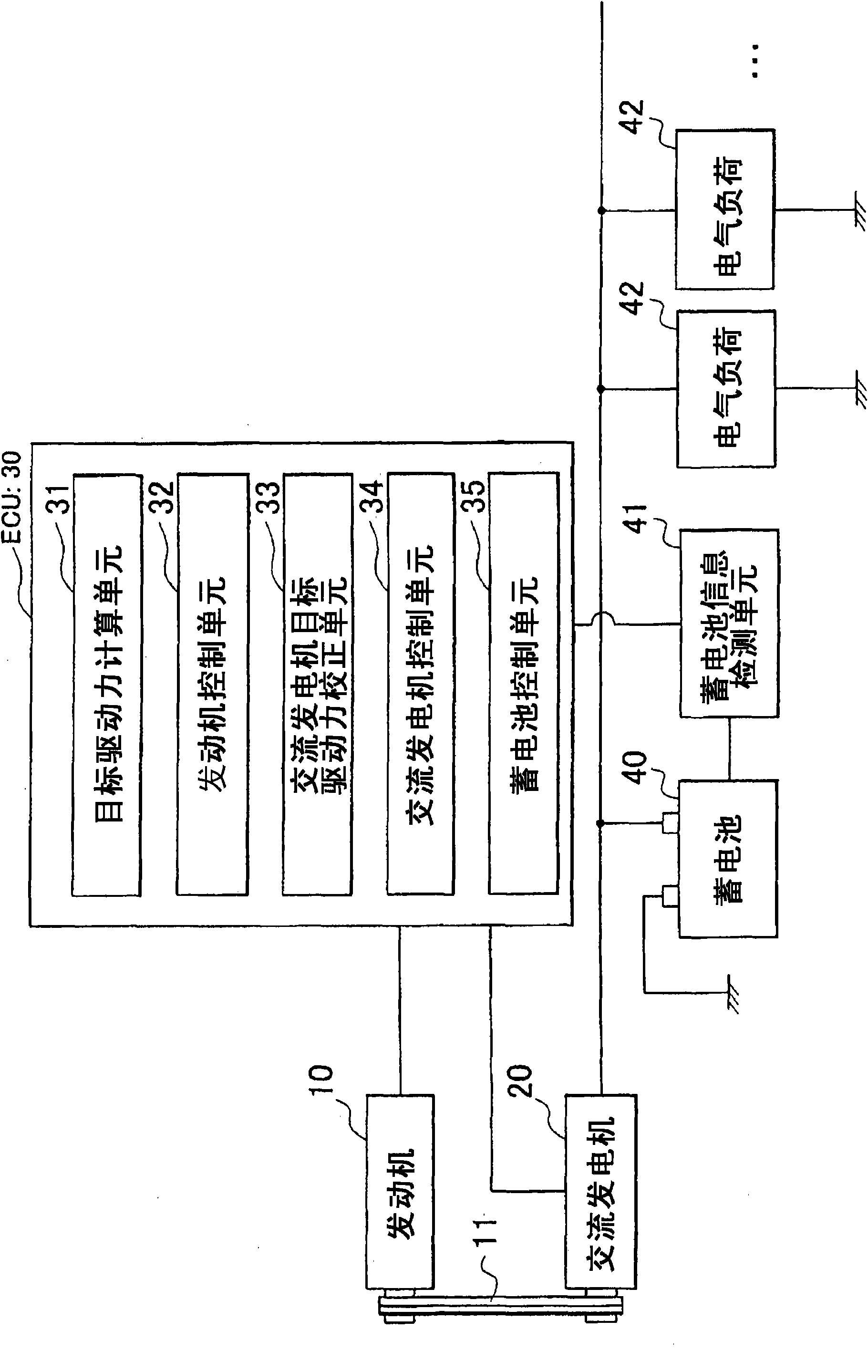
[0024] FIG. 1 is a view showing a structural example of a part of a vehicle to which a driving force control device for a vehicle according to the present invention is applied. In FIG. 1 , an engine 10 as a driving force generation source is, for example, a gasoline engine having a plurality of cylinders. Air is drawn into the combustion chamber of each cylinder through the intake passage, and fuel injected from the fuel injection valve is supplied to each combustion chamber. When a mixture of fuel and air is ignited by a spark plug, the mixture is combusted to reciprocate a piston, and then, a crankshaft, which is an output shaft of the engine 10, rotates. Exhaust gas generated by combustion of the mixture gas is discharged from each combustion chamber to an exhaust passage.

[0025] The driving force (torque) of the engine 10 is adjusted in such a manner that a throttle valve provided in the intake passage is driven by a throttle valve actuator such as an electric motor to ...


PUM


Abstract

An ECU (30) includes a target driving force calculating unit (31) and an alternator target driving force correcting unit (33). The target driving force calculating unit (31) calculates an alternator target driving force Fx _ac when an alternator (20) is used for controlling a driving force of a vehicle. The alternator target driving force correcting unit (33) corrects the alternator target driving force Fx _ac, which is calculated by the target driving force calculating unit (31), by adding a charging driving force Fx_dc that is used when the alternator (20) charges a battery (40) with a target battery voltage to determine an ultimate alternator target driving force Fx_ total.

Description

technical field [0001] The present invention relates to a driving force control device for a vehicle and a driving force control method for a vehicle, and more particularly, the present invention relates to a driving force control device for a vehicle that uses an alternator to control the driving force of a vehicle and a driving force control device for a vehicle. A driving force control method for a vehicle. Background technique [0002] Generally, engine torque is controlled using a throttle opening (intake air amount) and / or a fuel injection amount. The response delay of the intake system (the time delay until the air that has passed through the throttle valve is drawn into the cylinder) occurs until when the throttle valve opening changes (the change in the amount of air passing through the throttle valve) as a change in engine torque (A change in the amount of air that fills the cylinder) occurs. [0003] Japanese Patent Application Publication No. 2007-9885 (JP-A-20...

Claims


Application Information

Patent Timeline
Patent Type & Authority Applications(China)
IPC IPC(8): B60W10/08F02D29/06B60W10/26B60L50/16
CPCY02T10/6286B60W20/00B60L2240/423F02D29/06Y02T10/6226B60W2710/105Y02T10/7258B60K6/485B60W10/06B60W10/26Y02T10/642B60L2240/486B60W10/08B60W2710/083Y02T10/62Y02T10/64Y02T10/72B60W10/24
Inventor 能村真
Owner TOYOTA JIDOSHA KK
Why Eureka
Try Eureka