Grids for sintering pallet

A technology for sintering trolleys and grates, which is applied in the structural field of sintering trolleys and grates for metallurgical machinery. It can solve problems such as increasing production costs and affecting production efficiency, so as to prolong service life, improve production efficiency, and reduce U-turns. Effect

Inactive Publication Date: 2011-03-16
徐宏亮
View PDF0 Cites 1 Cited by
  • Summary
  • Abstract
  • Description
  • Claims
  • Application Information

AI Technical Summary

Problems solved by technology

If the grate bar falls off, material leakage and air leakage will occur, so it is necessary to stop frequently to replace the grate bar, which seriously affects the production efficiency and increases the production cost

Method used


Image

  • Grids for sintering pallet
  • Grids for sintering pallet
  • Grids for sintering pallet

Examples


Embodiment Construction

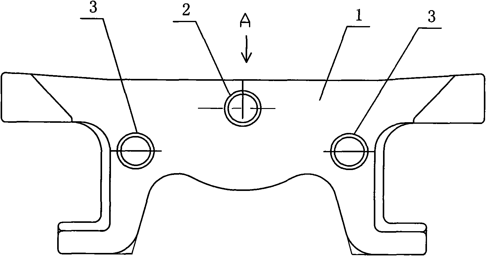
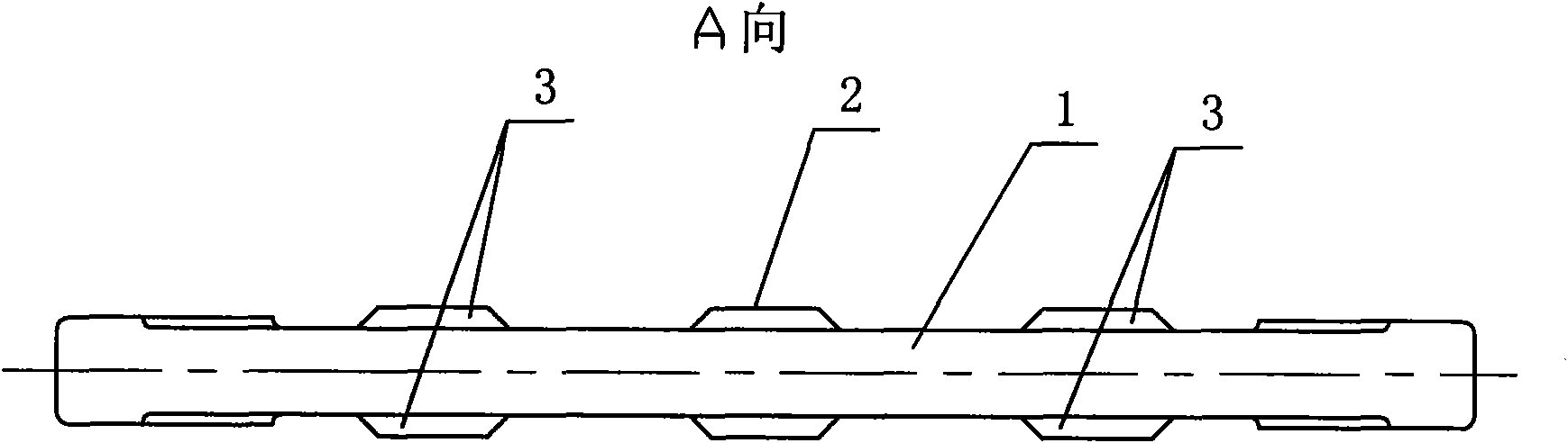
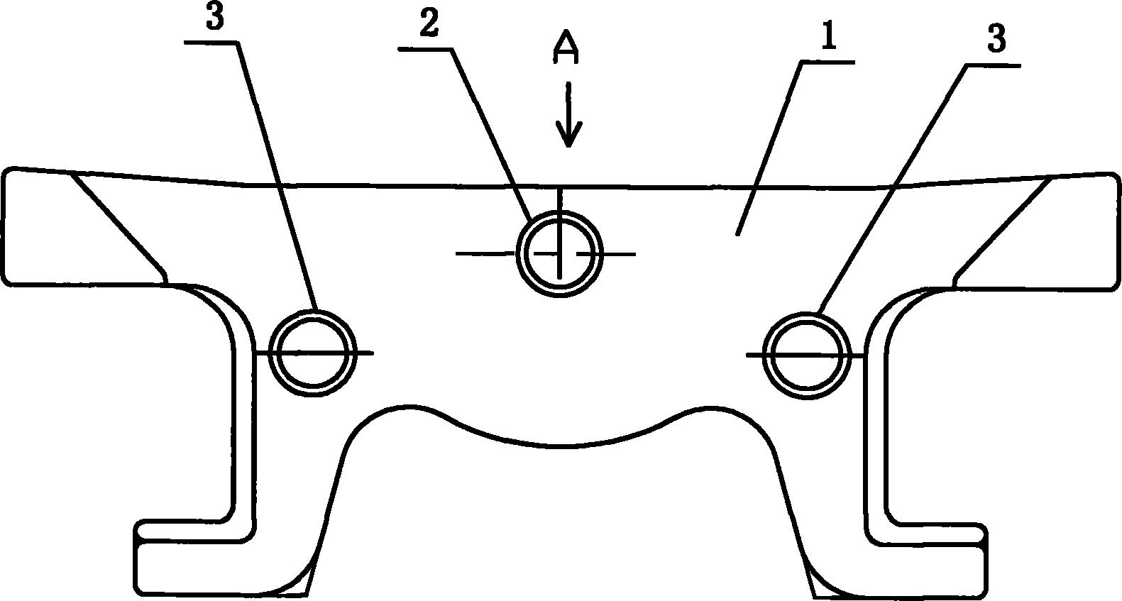
[0009] Such as figure 1 , 2 As shown, it is a grate bar for a sintering trolley, including a grate bar body 1, the two sides of the grate bar body 1 are respectively fixedly connected with the first bosses 2, and the two sides of each first boss 2 are respectively provided with second Bosses 3 , each second boss 3 is fixedly connected with the grate body 1 respectively, and the central horizontal line of each second boss 3 on the same side is lower than the central horizontal line of the first boss 2 .


PUM


Abstract

The invention discloses grids for a sintering pallet, which relates to the field of sintering pallet technical equipment of metallurgical machinery, in particular to the field of grid structure. Each grid comprises a grid body; two side surfaces of the grid body are fixedly connected with a first boss respectively; second bosses are arranged on the two sides of each first boss respectively; and each second boss is fixedly connected with the grid body. A second boss is added to each of the two sides of each boss, namely that each side surface has three bosses. The grids are closely arranged on the pallet and mutually extruded, thereby greatly reducing the probability of the grids for twisting left and right. The invention effectively reduces the probability of grids for turning and damage, prolongs the service life of the grids, reduces the grid replacing frequency, increases the production efficiency and lowers the production cost.

Description

technical field [0001] The invention relates to the technical equipment field of metallurgical mechanical sintering trolley, in particular to the structural field of grate bars. Background technique [0002] During the use of the grate bar, due to the uncertainty of the proportion of sintered material and the on-site industrial and mining conditions, it is relatively easy to produce sintered red ore. The temperature tolerance range of the bar material will cause the grate bar to be twisted and deformed. In severe cases, the hook of the grate bar will break due to stress concentration and the grate bar will fall off, commonly known as U-turn. Material leakage and air leakage will occur if the grate bar falls off, so frequent shutdowns are required to replace the grate bar, which seriously affects the production efficiency and increases the production cost. Contents of the invention [0003] The object of the present invention is to overcome the deficiencies of the prior ar...

Claims


Application Information

Patent Timeline
Patent Type & Authority Applications(China)
IPC IPC(8): F27B21/02F27B21/08
Inventor 徐宏亮
Owner 徐宏亮
Why Eureka
Try Eureka