Grid section for sintering trolley
A technology for sintering trolleys and grate bars, which is applied to the structure of grate bars and the technical equipment field of metallurgical machinery sintering trolleys, can solve problems such as increasing production costs, affecting production efficiency, etc., so as to extend service life, improve production efficiency, and reduce U-turns. Effect
Inactive Publication Date: 2011-03-16
徐宏亮
View PDF0 Cites 1 Cited by
- Summary
- Abstract
- Description
- Claims
- Application Information
AI Technical Summary
Problems solved by technology
If the grate bar falls off, material leakage and air leakage will occur, so it is necessary to stop frequently to replace the grate bar, which seriously affects the production efficiency and increases the production cost
Method used
View moreImage
Smart ImageViewing Examples

Examples
Embodiment Construction
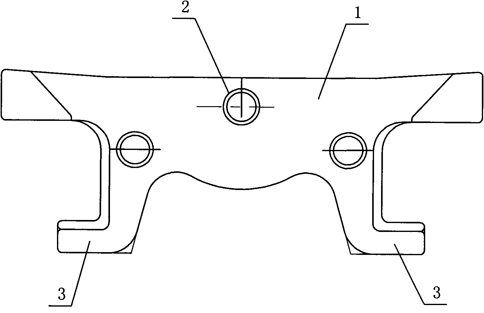
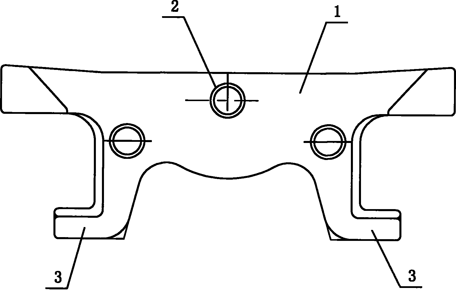
[0007] Such as figure 1 As shown, it is a grate bar for sintering trolley, which includes a grate bar body 1, three bosses 2 are fixedly connected to the two sides of the grate bar body 1, and the two sides of the lower end of the grate bar body 1 are respectively fixedly connected to hooks. Claw feet 3, the lower end surface of the grate bar body 1 between the two hooking claw feet 3 is an outwardly protruding arc surface.
Login to View More PUM
 Abstract
The invention discloses a grid section for a sintering trolley, which relates to the field of metallurgical machinery sintering trolley technical equipment, in particular to the field of grid section structures. The grid section comprises a grid section body, wherein at least one boss is fixedly connected to two side faces of the grid section body respectively; hook claws are fixedly connected to both sides of the lower end of the grid section body respectively; and the lower end face of the grid section body between the two hook claws is a circular surface which projects outwards. The lower part of the grid section is changed into a circular surface which bends downwards and the upward deformation and downward deformation of the circular surface are controlled by a method for increasing the sectional area of the middle part of the grid section. The turning and damage probabilities of the grid section are lowered greatly, the service life of the grid section is prolonged, the replacing frequency of the grid section is lowered, production efficiency is improved and production cost is lowered.
Description
technical field [0001] The invention relates to the technical equipment field of metallurgical mechanical sintering trolley, in particular to the structural field of grate bars. Background technique [0002] During the use of the grate bar, due to the uncertainty of the proportion of sintered material and the on-site industrial and mining conditions, it is relatively easy to produce sintered red ore. The temperature tolerance range of the bar material will cause the grate bar to be twisted and deformed. In severe cases, the hook of the grate bar will break due to stress concentration and the grate bar will fall off, commonly known as U-turn. Material leakage and air leakage will occur if the grate bar falls off, so frequent shutdowns are required to replace the grate bar, which seriously affects the production efficiency and increases the production cost. Contents of the invention [0003] The object of the present invention is to overcome the deficiencies of the prior ar...
Claims
Login to View More Application Information
Patent Timeline
 Patent Type & Authority Applications(China)
IPC IPC(8): F27B21/02F27B21/08
Inventor 徐宏亮
Owner 徐宏亮
Features
- R&D
- Intellectual Property
- Life Sciences
- Materials
- Tech Scout
- Unparalleled Data Quality
- Higher Quality Content
- 60% Fewer Hallucinations
Learn More Browse by: Latest US Patents, China's latest patents, Technical Efficacy Thesaurus, Application Domain, Technology Topic, Popular Technical Reports.
© 2025 PatSnap. All rights reserved.Legal|Privacy policy|Modern Slavery Act Transparency Statement|Sitemap|About US| Contact US: help@patsnap.com