
Side operation interlocking mechanism of electric control cabinet

A technology of electrical control cabinets and interlocking mechanisms, applied in the direction of cabinets/cabinets/drawer components, etc., can solve the problems of no interlocking mechanism, inconvenient operation, high order price, etc., to meet safety requirements and operate Simple and convenient, the effect of saving production cost

Inactive Publication Date: 2011-04-06
天津正本自控系统有限公司
View PDF0 Cites 0 Cited by
  • Summary
  • Abstract
  • Description
  • Claims
  • Application Information

AI Technical Summary

Problems solved by technology

[0002] With the development of the high and low voltage power distribution industry, its technical performance requirements for practicality and safety have been improved, and the interlock safety performance requirements for the operation of electrical control boxes and electrical control cabinets have also become higher and higher. The current electrical components themselves Without an interlock mechanism, the price of a separate order is relatively high, and there are many cases where the front door is interlocked, which is inconvenient to operate

Method used


Image

  • Side operation interlocking mechanism of electric control cabinet
  • Side operation interlocking mechanism of electric control cabinet
  • Side operation interlocking mechanism of electric control cabinet

Examples


Embodiment Construction

[0023] The specific implementation, structure, features and effects provided by the present invention will be described in detail below in conjunction with the accompanying drawings and preferred embodiments.

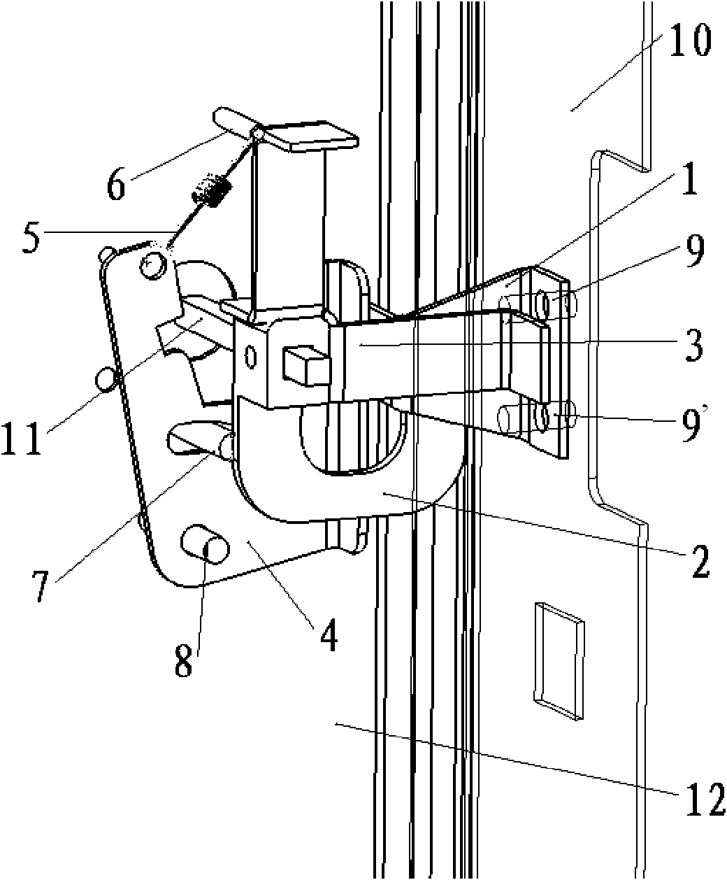
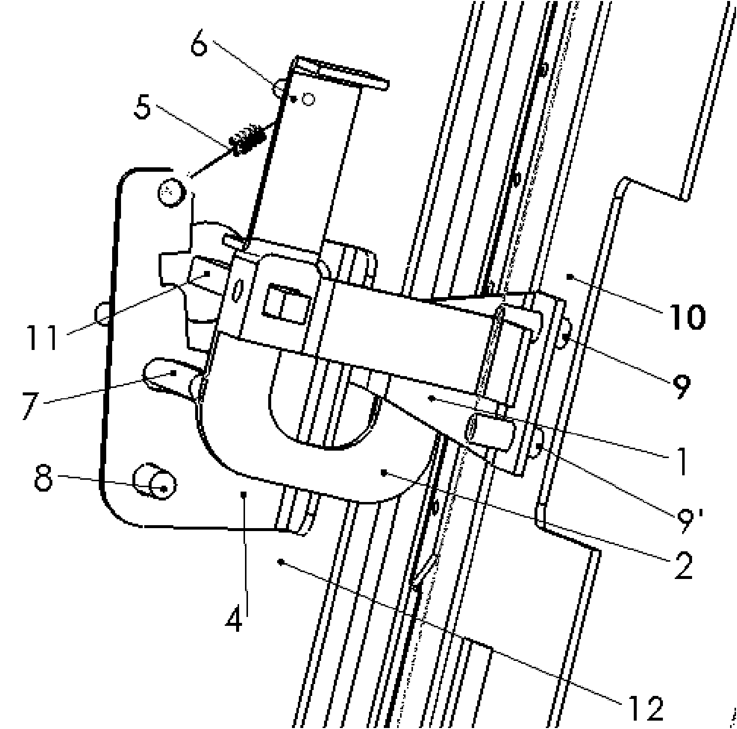
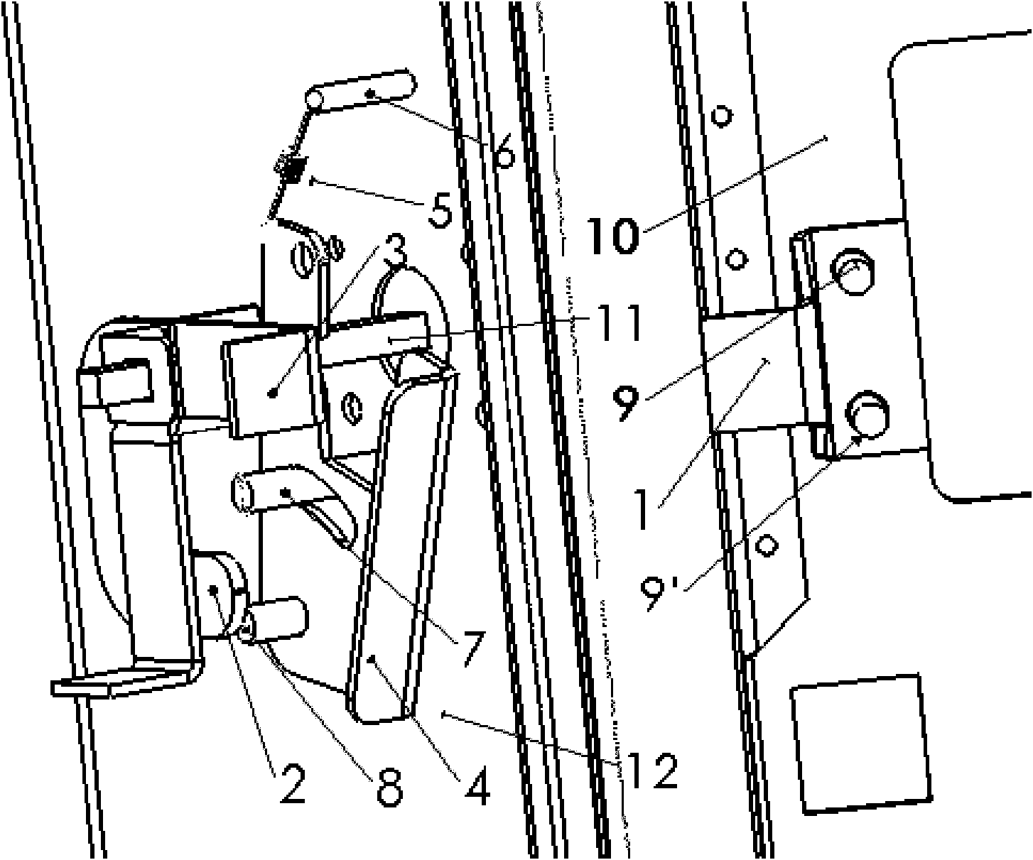
[0024] Such as Figure 1~7c The side operation interlocking mechanism of an electrical control cabinet shown includes a lock hook, a lock hook, a display bracket and a movable baffle. The lock hook 1 is provided with two round holes 21, 22, and through positioning Stud 9,9' is connected on the box door 10, has a square hole 13 on the lock hook 2, handle extension rod 11 penetrates wherein, has two threaded holes 14,15 on the edge of the lock hook, wherein one threaded hole 14 Fix the lock hook on the handle extension rod, install the display bracket 3 in another threaded hole 15; a round hole 20 is opened on the display bracket, fix the display bracket on the lock hook and rotate with the lock hook, and move the baffle plate 4 There are two round holes 16, 17, wherein ...


PUM


Abstract

The invention relates to a side operation interlocking mechanism of an electric control cabinet, which comprises a lock stop hook, a lock hanging hook, a display bracket and a movable baffle plate, wherein two round holes are arranged on the lock stop hook; the lock stop hook is connected with a cabinet door through a positioning stud; a square hole is arranged on the lock hanging hook; a handle extension rod is penetrated in the square hole; two threaded holes are arranged on the edge of the lock hanging hook; the lock hanging hook is fixed on the handle extension rod, and the display bracket is installed; a round hole is arranged on the display bracket; the display bracket is fixed on the lock hanging hook and rotates with the lock hanging hook; two round holes are arranged on the movable baffle plate, wherein one round hole is fixed on the positioning stud and used as a rotating shaft of the movable baffle plate, and the other round hole is connected with a tension spring to fix the tension spring on the movable baffle plate; the other end of the tension spring is fixed on the positioning stud on the side wall of the cabinet; an oblong hole is arranged on the movable baffle plate and matched with the positioning stud for spacing the movable baffle plate; and a groove is arranged on the movable baffle plate for locking the handle extension rod. The interlocking mechanism is simple and convenient for operation.

Description

technical field [0001] The invention belongs to the field of electric operation safety devices, and relates to an interlocking mechanism for side operation of an electric control cabinet, which is suitable for the interlocking of electric control boxes and external operations on the side of the electric control cabinet. Background technique [0002] With the development of the high and low voltage power distribution industry, its technical performance requirements for practicality and safety have been improved, and the interlock safety performance requirements for the operation of electrical control boxes and electrical control cabinets have also become higher and higher. The current electrical components themselves Without an interlock mechanism, the price of an individual order is relatively high, and there are many cases where the front door is interlocked, which is inconvenient to operate. There are few side-operated interlocking mechanisms in China, but now the safety p...

Claims


Application Information

Patent Timeline
Patent Type & Authority Applications(China)
IPC IPC(8): H05K5/02
Inventor 申随章申传飞
Owner 天津正本自控系统有限公司
Learn More