Disc flow allocation radial variable high pressure plunger pump

A technology of high-pressure plunger pump and flow distribution, which is applied in variable capacity pump components, components of pumping devices for elastic fluids, pumps, etc., can solve the problems of limited processing conditions, irreparable, complex structures, etc., and achieve Reduced manufacturing cost, repairability, ease of use, and improved volumetric efficiency

Inactive Publication Date: 2013-03-13
天津市泽华源泵业科技发展有限公司
View PDF0 Cites 7 Cited by
  • Summary
  • Abstract
  • Description
  • Claims
  • Application Information

AI Technical Summary

Problems solved by technology

[0002] At present, the traditional radial piston pumps at home and abroad mostly use two oil distribution methods - valve flow distribution or shaft flow distribution. Its structure is complex and difficult to process, especially the distribution shaft, which is limited by processing conditions and difficult to popularize.
Due to its irreparability after wear and tear, the product appears to be more expensive in general use

Method used


Image

  • Disc flow allocation radial variable high pressure plunger pump
  • Disc flow allocation radial variable high pressure plunger pump
  • Disc flow allocation radial variable high pressure plunger pump

Examples


Embodiment Construction

[0017] The specific implementation, structure, features and effects provided by the present invention will be described in detail below in conjunction with the accompanying drawings and preferred embodiments.

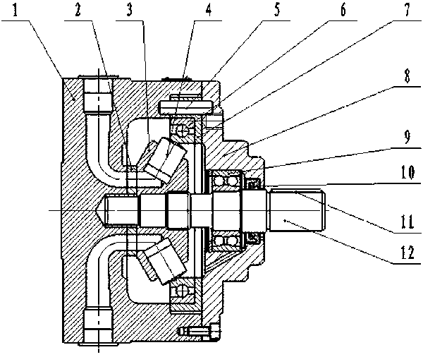
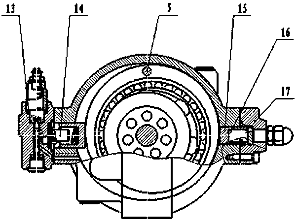
[0018] Such as Figure 1~4 A radial variable high-pressure plunger pump with plate flow distribution shown includes a pump body, a pump cover, a rotor, a stator and a plunger. The oil distribution plate 2 is a circular oil distribution plate. The oil window 18, the static pressure support sealing belt 19 and the silencer groove 20, the oil distribution plate, the pump body 1 and the rotor 3 are combined to form an oil passage. When in use, these three parts are closely connected to generate oil flow and boost pressure. The plunger holes on the rotor are radially arranged, the flow distribution surface of the rotor is closely attached to the flow distribution plate, and the plunger holes are set to form an angle with the axis of the transmission shaft 12, which makes the...


PUM


Abstract

The invention relates to a disc flow allocation radial variable high pressure plunger pump. An oil allocation disc refers to a circular oil allocation disc; an oil-through window, a static pressure support seal belt and a noise reduction groove are arranged in the oil allocation disc; an oil-through channel is formed by combining the oil allocation disc with a pump body and a rotor; plunger holes in the rotor are arranged in the radial direction; the flow allocation plane of the rotor is tightly adhered to the flow allocation disc; the plunger holes are designed into that an inclined angle is formed between the plunger holes and the axis of a transmission shaft; plungers are installed inside the plunger holes of the rotor; a hinge pin is tightly assembled on the pump body and is in clearance fit with an assembling hole in a stator; a rotating bearing is installed on a pump cover; a shaft seal is installed on the transmission shaft; a variable mechanism comprises a variable plunger which is matched with a limiting plunger, a limiting spring and a limiting body. As a disc flow allocation structure is adopted, the disc flow allocation radial variable high pressure plunger pump has simplified design and repairability, is low in manufacturing cost and convenient to use; as steel pieces can be used, the selection range of materials is expanded, and the standardization and generality of working are facilitated; and the performance of an original reusing pump and the system optimization are improved with relatively less transforming cost.

Description

technical field [0001] The invention belongs to the field of power components of hydraulic transmission, and relates to a radially variable high-pressure plunger pump with disk flow distribution. Background technique [0002] At present, traditional radial piston pumps at home and abroad mostly use two oil distribution methods—valve distribution or shaft distribution. The structure is complex and difficult to process, especially the distribution shaft, which is limited by processing conditions and difficult to popularize. Due to its irreparability after wear, the product appears to be more expensive in general use. Contents of the invention [0003] The problem to be solved by the present invention is to overcome the deficiencies of the prior art and provide a disc flow radial variable high-pressure plunger pump. The oil distribution disc can be made of alloy steel, which has strong wear resistance and has Certain repairability, the processing is basically conventional ma...

Claims


Application Information

Patent Timeline
Patent Type & Authority Applications(China)
IPC IPC(8): F04B1/04F04B53/10
Inventor 董桂敏
Owner 天津市泽华源泵业科技发展有限公司
Why Eureka
Try Eureka