Water-cooled machine water jacket structure and press mounting technology

A water jacket and pressure technology, which is applied in electromechanical devices, cooling/ventilation devices, and manufacturing motor generators, etc., can solve problems such as poor machining accuracy, low production efficiency, and difficult sand cleaning, and achieve low manufacturing costs and high processing efficiency. High, beautiful appearance effect

Inactive Publication Date: 2013-08-14
TIANJIN SANTROLL ELECTRIC AUTOMOBILE TECH CO LTD
View PDF5 Cites 8 Cited by
  • Summary
  • Abstract
  • Description
  • Claims
  • Application Information

AI Technical Summary

Problems solved by technology

[0002] When the motor is working, it will generate a lot of heat, which needs to be discharged in time. At present, the water jacket casing mainly adopts integral casting, coil welding and other processes, but due to the structural characteristics of the water jacket, its production efficiency is not high, the processing accuracy is poor, and the process cost is relatively high. High, unsightly appearance and other issues
Specifically, there are the following defects: due to the structure of the water channel, it is difficult to clean the sand after the integral casting water jacket casing, which affects the heat exchange capacity between the casing and the cooling liquid
Welding of coiled plates The casing of the water jacket needs to be welded. After welding, it needs to be annealed to relieve stress, and the welds are prone to problems such as cracks, incomplete penetration, slag inclusions, pores, and tumors. Impression The tightness and aesthetics of the water jacket

Method used


Image

  • Water-cooled machine water jacket structure and press mounting technology
  • Water-cooled machine water jacket structure and press mounting technology
  • Water-cooled machine water jacket structure and press mounting technology

Examples


Embodiment Construction

[0024] The specific embodiments of the present invention are described below with reference to the accompanying drawings. The embodiments of the present invention will be described in further detail below with reference to the accompanying drawings. The following description of the embodiments of the present invention is only exemplary and is not intended to limit the subject matter of the present invention. For the described embodiments of the present invention, there are other changes within the protection scope of the claims, which all belong to the subject of the present invention.

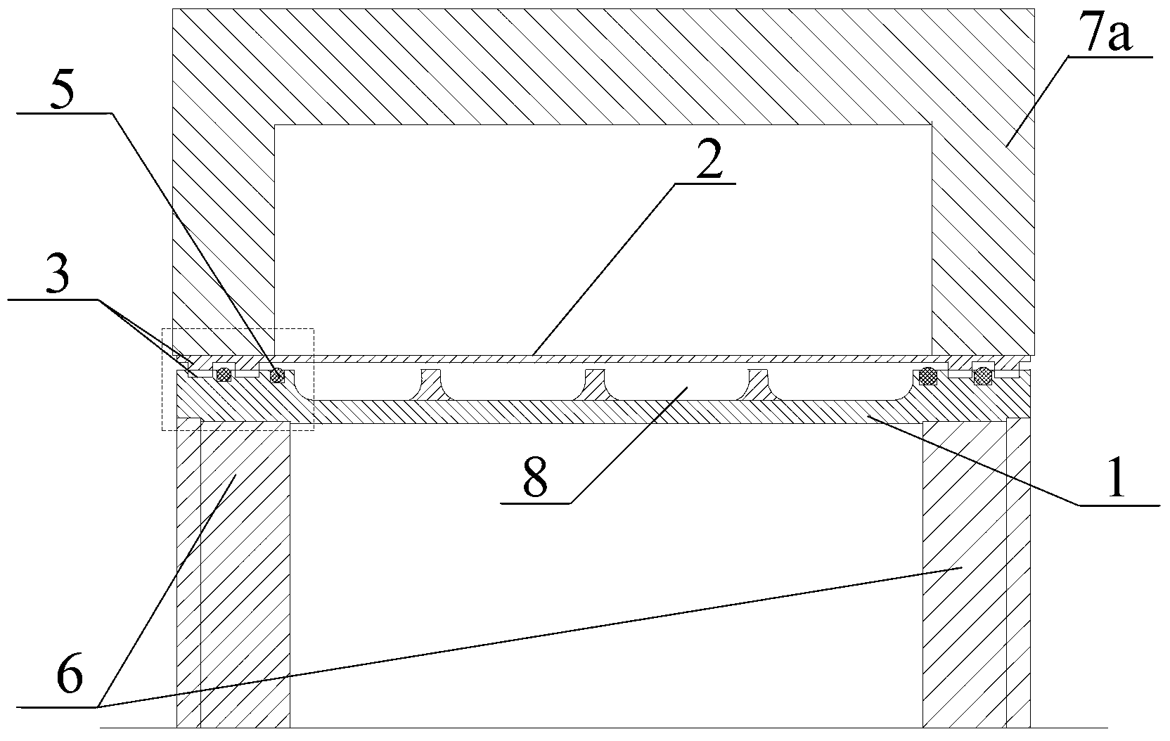
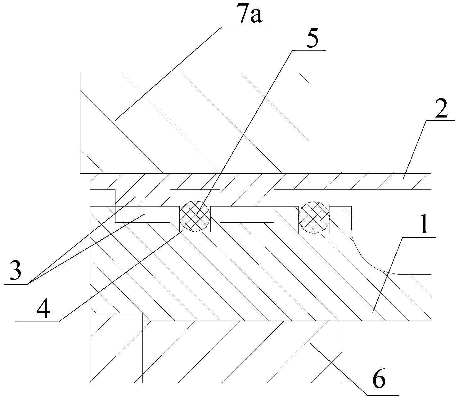
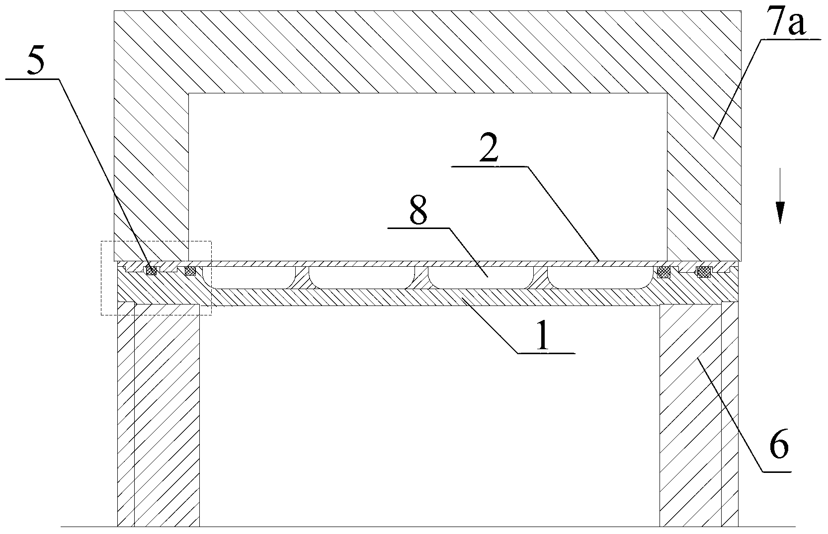
[0025] Such as Figure 1 to Figure 5 As shown, 1 is the inner shell, 2 is the outer shell, 3 is the male and female teeth, 4 is the sealing groove, 5 is the sealing ring, 6 is the mold, 7 is the upper and lower press tooling, 7a is the lower press tool, and 7b is the upper press Tooling, 8 is a waterway. For the sake of simplicity, the figure does not mark each male and female tooth, sealing gro...


PUM


Abstract

The invention discloses a machine water jacket structure and a press mounting technology. Each of the two ends of each of an inner casing and an outer casing of the water jacket is provided with one or more yin-yang teeth formed by circular raised grooves or dented grooves; the yin-yang teeth on the inner casing and the yin-yang teeth on the outer casing can be embedded into each other and meshed with each other; each of the two ends of each of the inner casing and the outer casing is provided with one or more circular sealing grooves; the sealing grooves are located on the yin-yang teeth; a sealing ring is located in each sealing groove; the inner casing is located on the fixed mould; the sealing ring is embedded in the inner casing or the sealing grooves at two ends of the outer casing; the inner casing is sleeved with the outer casing, and the outer casing is subjected to axial localization; and the upper and lower pressure tooling is started to cause the yin-yang teeth of the outer casing and the inner casing to be meshed with each other, and the sealing ring is tightly pressed to fill the sealing grooves to achieve sealing. The machine water jacket structure and press mounting technology disclosed by the invention aims to overcome the deficiency in the prior art, and to provide a machine water jacket structure and press mounting technology which can increase the production efficiency and machining accuracy and reduce the technology cost.

Description

Technical field [0001] The invention belongs to the field of motor structures, and particularly relates to a motor water jacket structure through embedded gearing and its press-fitting process. Background technique: [0002] A large amount of heat is generated when the motor is working and needs to be discharged in time. At present, the water jacket casing mainly adopts integral casting, coil welding and other processes. However, due to the structural characteristics of the water jacket, its production efficiency is low, processing accuracy is poor, and the process cost is relatively high. High and unsightly appearance. The specific defects are as follows: the integrally cast water-jacketed casing is difficult to clean sand after forming due to the structure of the water channel, which affects the heat exchange capacity between the casing and the coolant. Coil welding water jacket housing needs to be welded, and annealing stress relief treatment is required after welding, and th...

Claims


Application Information

Patent Timeline
Patent Type & Authority Applications(China)
IPC IPC(8): H02K9/19H02K5/20H02K15/14H02K5/10
Inventor 胡淼张金毅
Owner TIANJIN SANTROLL ELECTRIC AUTOMOBILE TECH CO LTD
Why Eureka
Try Eureka