Blowing based fuselage high incidence pitching moment control method

A technology of pitching moment and control method, which is applied in the field of aerospace and can solve problems such as unseen fuselage pitching moment

Active Publication Date: 2011-04-13
BEIHANG UNIV
View PDF5 Cites 4 Cited by
  • Summary
  • Abstract
  • Description
  • Claims
  • Application Information

AI Technical Summary

Problems solved by technology

At present, there is no method to control the pitching moment of the fuselage by blowing air in domestic and foreign research.

Method used


Image

  • Blowing based fuselage high incidence pitching moment control method
  • Blowing based fuselage high incidence pitching moment control method
  • Blowing based fuselage high incidence pitching moment control method

Examples


Embodiment Construction

[0011] The purpose of the invention is to provide a method for controlling the pitching moment of the fuselage based on air blowing. In the present invention, air blowing control is performed by setting air blowing slots on the leeward side of the fuselage, so that the pitching moment of the fuselage in the range of high angle of attack can be less than zero, and the effective control of the pitching moment of the fuselage at high angle of attack can be realized. The specific technical scheme is as follows:

[0012] The air blowing-based airframe pitching moment control method at high angle of attack, the steps are as follows:

[0013] Step 1: Determine the range of angle of attack for fuselage blowing control

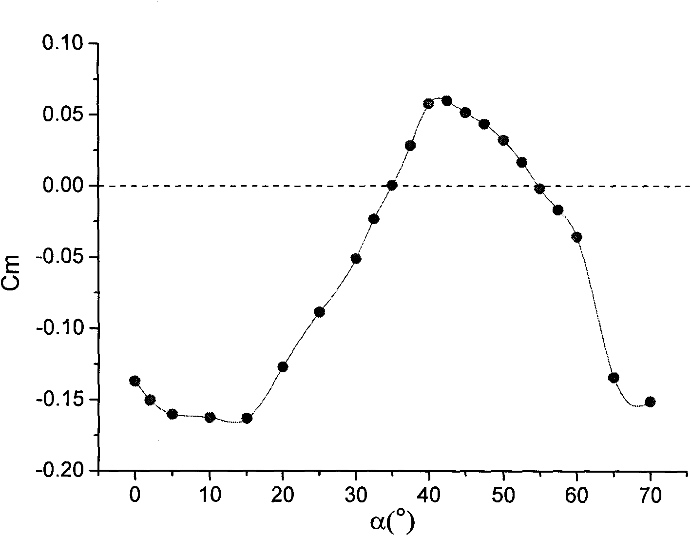
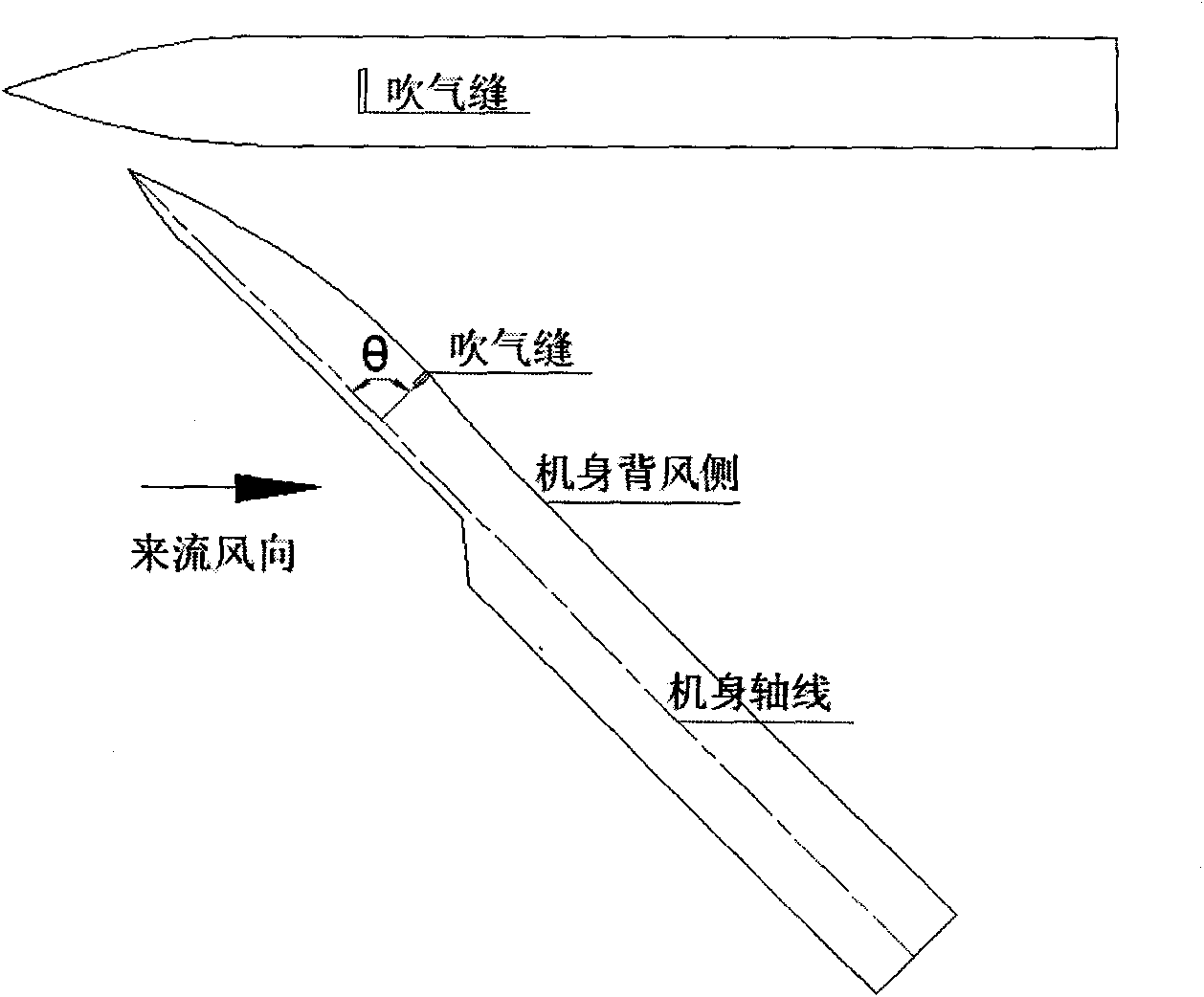
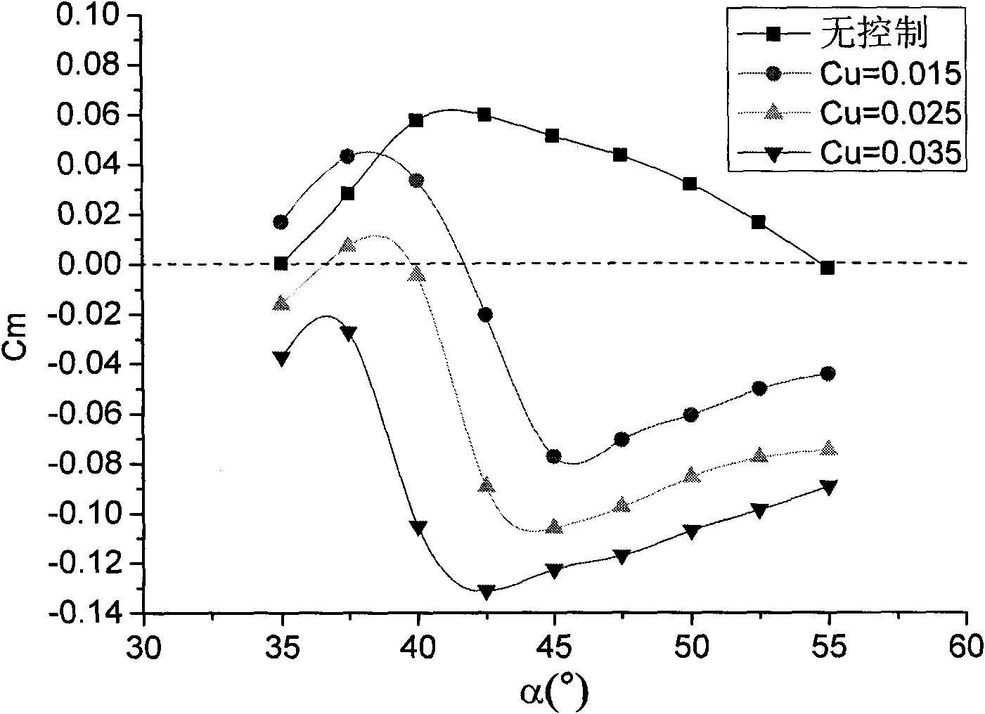
[0014] The characteristics of the fuselage pitching moment at high angle of attack are studied by means of wind tunnel force measurement, and the variation curve of the fuselage pitching moment with the angle of attack is obtained, as shown in figure 1 Show. The ran...


PUM


Abstract

The invention discloses a blowing based fuselage high incidence pitching moment control method, aiming at overcoming the defect that nose-up torque of the modern fighter fuselage when in high incidence maneuvering is over high. Incidence range for implementing blowing control is determined, a blowing seam is set, and pitching moment is controlled, thus realizing effective control on fuselage highincidence pitching moment.

Description

technical field [0001] The invention relates to a method for controlling the pitching moment of a fuselage at a high angle of attack by means of air blowing, and belongs to the technical field of aerospace. Background technique [0002] In order to strive for air superiority, modern fighter jets have higher and higher requirements for maneuverability. In order to improve the maneuverability of aircraft, especially the maneuverability at high angles of attack, modern fighters generally adopt the design idea of ​​relaxing static stability, such as the famous American F-16 and F-18 fighters, and Russian Su-27 fighters. A highly maneuverable fighter with a relaxed static stability design, the focus is before the center of gravity, and the aircraft is statically unstable. During flight, the active control system (that is, the automatic stabilization system) controls the corresponding rudder surface to ensure the stability of the aircraft. Because of this static instability desig...

Claims


Application Information

Patent Timeline
Patent Type & Authority Applications(China)
IPC IPC(8): B64C13/00G05D17/02
Inventor 邓学蓥王延奎董超石伟田伟马宝峰
Owner BEIHANG UNIV
Why Eureka
Try Eureka