Data transmission method

A data transmission method and data technology, applied in the field of data coding, can solve the problems of high phase hopping probability and reduce phase hopping probability, and achieve the effect of concentrated signal spectrum energy and narrow spectrum

Active Publication Date: 2011-05-11
天津鲲鹏信息技术有限公司
View PDF3 Cites 4 Cited by
  • Summary
  • Abstract
  • Description
  • Claims
  • Application Information

AI Technical Summary

Problems solved by technology

[0006] The main purpose of the present invention is to provide a data encoding method applied to the tag side in the passive radio frequency identification system, which can reduce the phase jump probability between the encoded waveforms of two adjacent binary data in the encoding, so as to solve the problem of existing encoding In the method, there is a problem that the phase jump probability between the encoded waveforms of two adjacent binary data is high

Method used


Image

  • Data transmission method
  • Data transmission method
  • Data transmission method

Examples


Embodiment Construction

[0040] The encoding method of the present invention will be described in detail below with reference to the drawings and embodiments.

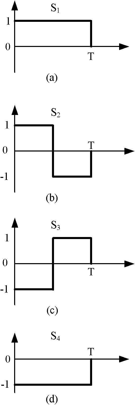
[0041] figure 1 A schematic diagram of binary data encoding baseband symbols provided for a specific embodiment of the present invention, wherein the abscissa of each figure is the time axis, and the ordinate is the amplitude axis. (a) in the figure indicates a high level S with no intermediate phase jump 1 , (b) represents the falling edge S of the intermediate phase jump 2 , (c) represents the rising edge S of the intermediate phase jump 3 , (d) indicates the low level S with no jump in the middle phase 4 . Technical scheme 1 provided by the present invention is to use binary data 1 with S 2 or S 3 Encoding, use S for binary data 0 1 or S 4 coding; technical scheme 2 is to use S for binary data 0 2 or S 3 Encoding, binary data 1 with S 1 or S 4 coding.

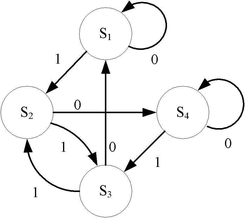
[0042] figure 2 The binary data encoding state transition diagram provide...


PUM


Abstract

The invention provides a data encoding method applied to a label end in a passive radio frequency identification system. According to the technical scheme, binary data 0 and binary data 1 are encoded in same length, wherein if the binary data 1 is encoded in the manner of jumping the middle phase, the binary data 0 is encoded in the manner of not jumping the middle phase, and if the binary data 0is encoded in the manner of jumping the middle phase, the binary data 1 is encoded in the manner of not jumping the middle phase. Through the data encoding method provided by the invention, the phasejump probability between the encoding waveforms of two adjacent binary data in the encoding process can be reduced so as to solve the problem that the phase jump probability between the encoding waveforms of two adjacent binary data is relatively high in the traditional encoding method.

Description

[0001] technical field [0002] The invention belongs to the technical field of radio frequency identification communication, and in particular relates to a data encoding method applied in a radio frequency identification system. Background technique [0003] Radio Frequency Identification (RFID) communication technology is a non-contact automatic identification technology; the radio frequency identification system is mainly composed of tags, readers and computer network systems. The reader communicates with the tag through radio frequency signals, obtains the identification information stored on the tag, and at the same time manages and transmits the read tag information through the computer network system. [0004] RFID systems can be divided into two categories: passive RFID systems and active RFID systems, the main difference between the two is the label side. The tags of the passive RFID system need to obtain energy from the RF signal emitted by the reader, while the t...

Claims


Application Information

Patent Timeline
Patent Type & Authority Applications(China)
IPC IPC(8): H03M7/12
Inventor 李建成任天鹏王宏义庄钊文唐朝京许拔
Owner 天津鲲鹏信息技术有限公司
Why Eureka
Try Eureka