
High-rise descent control device based on hydraulic damping

A technology for hydraulic damping and high-rise buildings, applied in life-saving equipment, building rescue, etc., can solve the problems that the hydraulic device cannot provide damping force smoothly, cannot realize the speed regulation function, and reduce the stability of the mechanism, etc., and achieves simple processing and assembly. Simple, smooth-running effect

Inactive Publication Date: 2012-08-29
NAT UNIV OF DEFENSE TECH
View PDF4 Cites 0 Cited by
  • Summary
  • Abstract
  • Description
  • Claims
  • Application Information

AI Technical Summary

Problems solved by technology

However, when the hydraulic device in the existing high-rise slow-down device used for escape works, the volume of the internal hydraulic oil changes, which will cause empty travel or jamming; the profile of the internal cam matched with the hydraulic device is a regular hexagon or an eccentric circle, When the cam rotates, the hydraulic device cannot provide damping force smoothly, which reduces the stability of the mechanism
[0006] None of the mechanisms listed above can realize the speed regulation function, and they cannot adapt to people or objects with different gravity through the adjustment device. In addition, the structures of the above-mentioned mechanisms are relatively complicated and the cost is relatively high.

Method used


Image

  • High-rise descent control device based on hydraulic damping
  • High-rise descent control device based on hydraulic damping
  • High-rise descent control device based on hydraulic damping

Examples


Embodiment Construction

[0033] The present invention will be described in further detail below in conjunction with the accompanying drawings and specific embodiments.

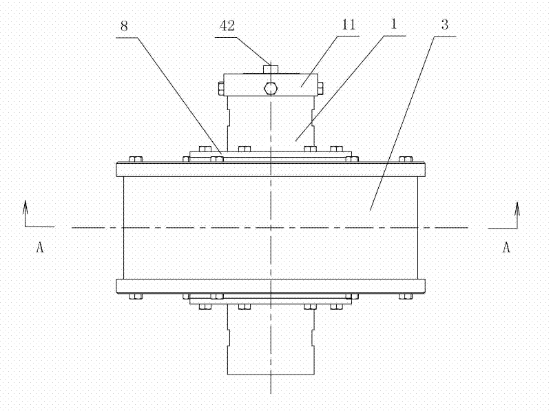
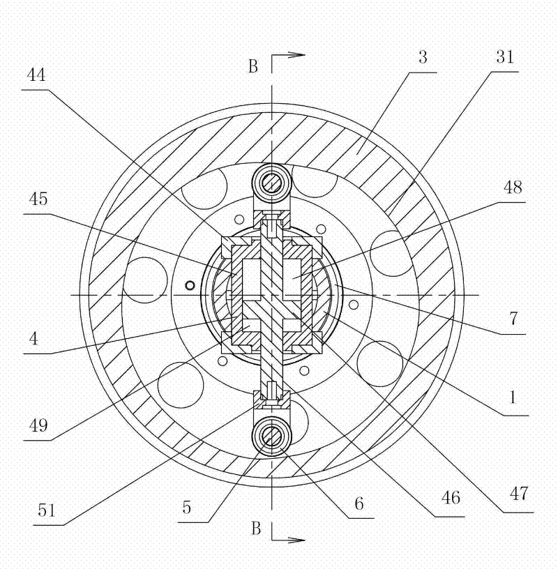
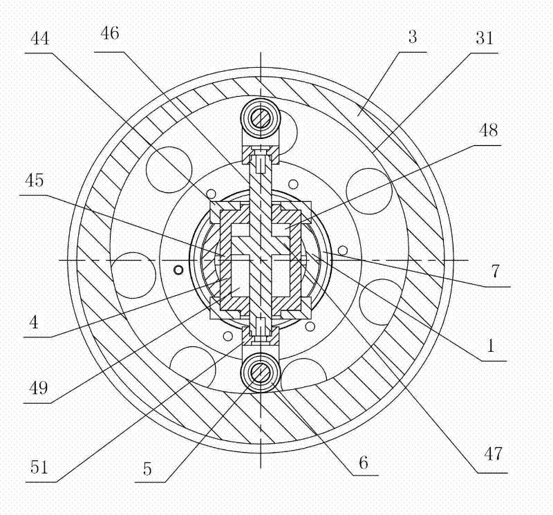
[0034] Such as figure 1 , figure 2 , image 3 and Figure 4 As shown, the high-rise slow-down device based on hydraulic damping of the present invention includes a main shaft 1, a rope 2 and an inner cam 3, the inner cam 3 is installed on the main shaft 1, and the rope 2 is wound on the outer cylindrical surface of the inner cam 3, A hydraulic cylinder 4 is arranged in the inner cam 3, and the piston rod 46 of the hydraulic cylinder 4 is driven to expand and contract by the cam wall 31 of the inner cam 3. The hydraulic cylinder 4 is connected with a damping oil circuit 41 which can adjust the telescoping speed of the piston rod 46. The high-rise slow-down device of the present invention drives the rope 2 to pull the inner cam 3 to rotate through gravity, so that the cam wall 31 of the inner cam 3 drives the piston rod 46 of the hy...


PUM


Abstract

The invention discloses a high-rise descent control device based on hydraulic damping, which comprises a main shaft, a rope and an inner cam, wherein the inner cam is arranged at the main shaft, the rope is wound on the outer cylindrical surface of the inner cam, the inside of the inner cam is provided with a hydraulic cylinder, the piston rod of the hydraulic cylinder is driven by the cam wall of the inner cam to reciprocate, and the hydraulic cylinder is connected with a damping oil way which can adjust the reciprocating speed of the piston rod. The device of the invention has the advantages that the structure is simple and compact, the stability is good, the efficiency is high, the device is safe and reliable to use, the machining and assembly process is simple, the maintenance cost islow, the application range is wide, and the like.

Description

technical field [0001] The invention relates to a device for releasing heavy objects from high buildings or for people to escape from high buildings, in particular to a hydraulic damping-based slow-falling device for high buildings. Background technique [0002] At present, high-rise buildings are generally equipped with high-rise slow-down devices, which are often used to release heavy objects from high-rise buildings or to facilitate personnel to escape from high-rise buildings when a fire breaks out. The key to the design of the high-rise slow-descent device used for escape is to ensure the escape efficiency and the safety of personnel, so the electrical control device should be reduced as much as possible to improve its safety. Usually, the device is improved by cleverly using the mechanism for special design. Escape efficiency and safety. Existing slow-descent devices for high-rise buildings that are used for escape can be divided into the following categories in princ...

Claims


Application Information

Patent Timeline
Patent Type & Authority Patents(China)
IPC IPC(8): A62B1/12
Inventor 崔红娟董培涛辛瑜张汇泉袁林罗强峻陶溢苏剑彬
Owner NAT UNIV OF DEFENSE TECH
Learn More