
Method for calculating strength of main shaft of wind turbine generator set

A wind power generation unit, strength calculation technology, applied in the direction of calculation, electrical digital data processing, special data processing applications, etc., can solve the problems of increased structural size, insecurity, performance impact and transmission, etc., to achieve cost saving and accurate calculation , time-saving effect

Inactive Publication Date: 2011-05-25
锋电能源技术有限公司
View PDF2 Cites 11 Cited by
  • Summary
  • Abstract
  • Description
  • Claims
  • Application Information

AI Technical Summary

Problems solved by technology

It can be seen that the main shaft is the core transmission part of the wind turbine, and its performance affects the coordinated transmission and operation of various parts on the shaft, thereby affecting the working conditions of the entire mechanism. Especially under high-load operation, the strength of the main shaft is even more important. ; Therefore, in order to avoid unstable and unsafe factors in the working state of the main shaft, it is often necessary to calculate the strength of the main shaft, which is generally calculated by the formulas provided by material mechanics, theoretical mechanics and elastic mechanics, and many of them Simplified conditions make the calculation accuracy very low
In order to ensure the safe and reliable operation of the main shaft, the method of increasing the safety factor is often adopted, but the result is an increase in structural size, waste of materials, and sometimes a reduction in structural performance

Method used


Image

  • Method for calculating strength of main shaft of wind turbine generator set
  • Method for calculating strength of main shaft of wind turbine generator set
  • Method for calculating strength of main shaft of wind turbine generator set

Examples


Embodiment Construction

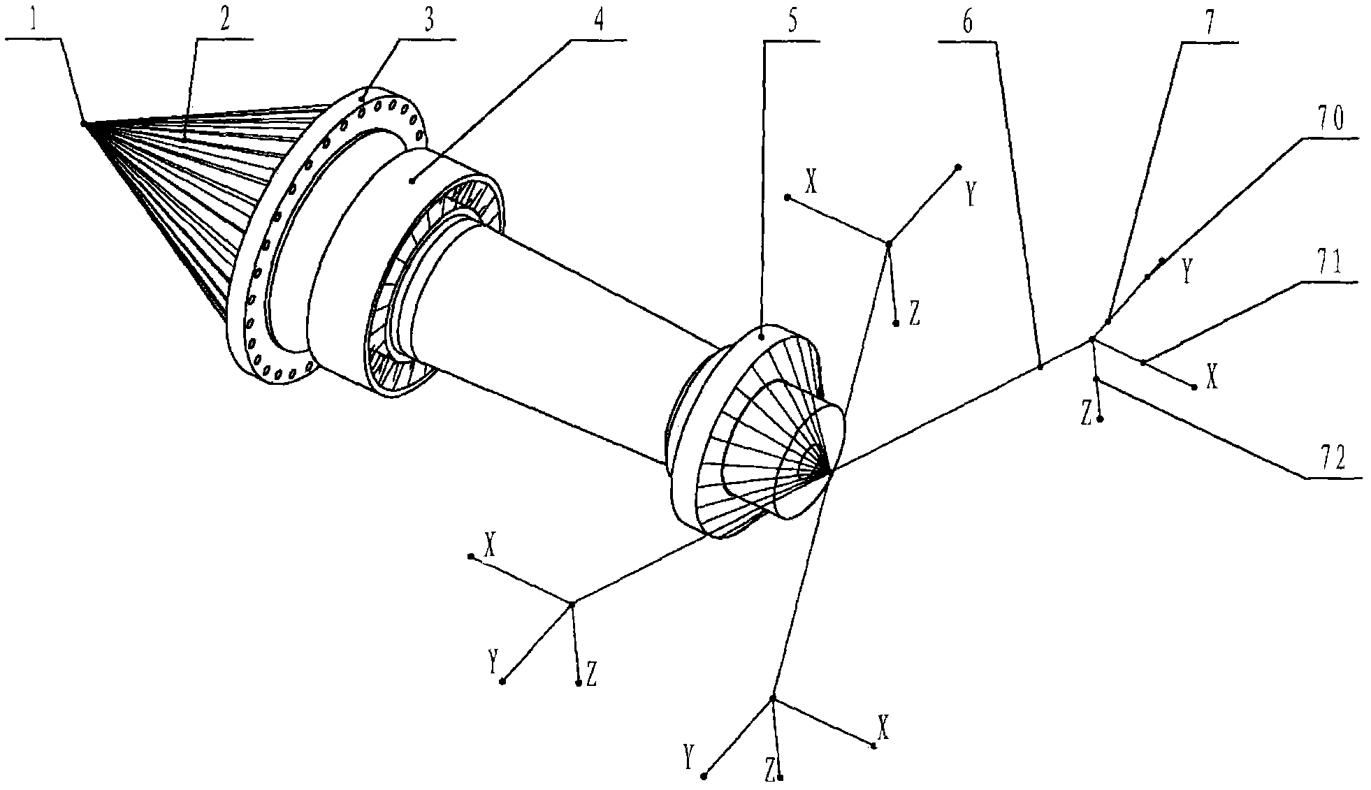
[0019] Such as figure 1 As shown, the method for calculating the main shaft strength of the wind power generating set according to the present invention, its steps mainly include:

[0020] (1) Using the existing finite element software as a platform to implement modeling, firstly, the main shaft 3, bearing 4 and locking disc 5 are combined into one structure with solid element simulation settings, and the solids can be combined by node merging. The bearing 4 and the locking disc 5 are solidly modeled, which can effectively reduce the stress concentration problem at the contact position; the wind wheel part is simulated to set a wind wheel node 1 and its position is the center point of the wind wheel;

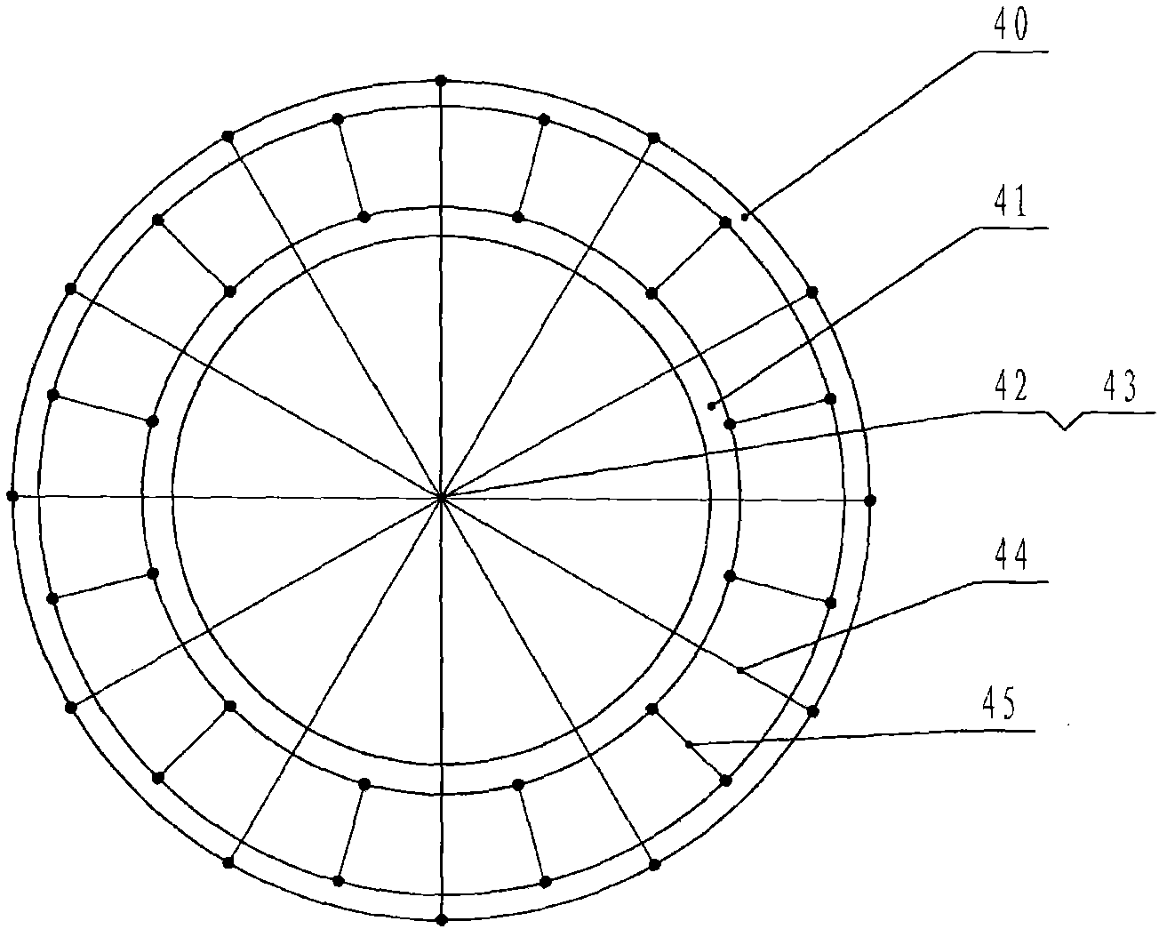
[0021] (2) Secondly, four gear box elastic supports are arranged outside the locking disc 5, and the elastic support of each gear box is simulated by the spring unit group 7, and the flange bolt holes of the wind wheel node 1 and the main shaft 3 are connected by the rigid beam ...


PUM


Abstract

The invention relates to a method for calculating the strength of a main shaft of a wind turbine generator set, modeling is implemented for a platform through existing finite element software, material attributes of all parts are finally defined, calculation is performed, and a deformation and stress cloud atlas is obtained; the modeling process mainly comprises the steps of using a solid unit to set and merge the main shaft, a bearing and a locking disk into an integrated structure in a simulating manner, arranging four gear box elastic supports outside the locking disk, using a spring unit group to simulate each gear box elastic support, connecting nodes of a wind wheel with all flange bolt holes of the main shaft through a rigid beam unit I, and connecting the locking disc with the spring unit group through a rigid beam unit II; and applying external loads on the nodes of the wind wheel, applying all constraints on the spring unit group and applying position constraints on the bearing. The method has the benefits of being conductive to precisely calculating the strength performance of the main shaft, being capable of simultaneously calculating multiple working conditions, being conductive to saving time and saving cost, and being very applicable to large-scale popularization.

Description

technical field [0001] The invention relates to the technical field of wind power generation, in particular to a method for calculating the main shaft strength of a wind power generating set. Background technique [0002] As we all know, the current mainstream horizontal-axis wind turbines adopt double-fed wind turbines supported by single bearings. The main transmission structure is that a wind wheel is installed at the front end of the main shaft, the rear end is connected with the gearbox, and the middle is fixed by a bearing. The rotational torque of the wind wheel is transmitted to the gearbox through the main shaft, and then passed to the generator to generate electricity after the gearbox is increased in speed; the main shaft not only transmits the torque of the wind wheel in the wind turbine, but also bears the weight of the wind wheel and other load. It can be seen that the main shaft is the core transmission component of the wind turbine, and its performance affec...

Claims


Application Information

Patent Timeline
IPC IPC(8): G06F17/50
Inventor 杨磊
Owner 锋电能源技术有限公司
Learn More