
Method used for liquid crystal dripping

A technology of liquid crystals and liquid crystal drops, applied in nonlinear optics, instruments, optics, etc., can solve problems such as spots and defects on the screen

Inactive Publication Date: 2011-06-15
TOP ENG CO LTD
View PDF4 Cites 0 Cited by
  • Summary
  • Abstract
  • Description
  • Claims
  • Application Information

AI Technical Summary

Problems solved by technology

The difference in thickness of the liquid crystal layer makes the path of light passing through the liquid crystal layer different, which in turn causes spots on the screen of the product and causes defective products

Method used


Image

  • Method used for liquid crystal dripping
  • Method used for liquid crystal dripping
  • Method used for liquid crystal dripping

Examples


Embodiment Construction

[0020] Hereinafter, preferred embodiments of the present invention will be described in detail with reference to the accompanying drawings.

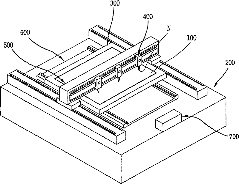
[0021] In the method for dropping liquid crystals according to a preferred embodiment of the present invention, liquid crystals are dropped, liquid crystals are introduced into LC supply paths, and liquid crystals are passed through nozzles by spraying gas toward liquid crystals forming liquid crystal droplets on nozzle ends.

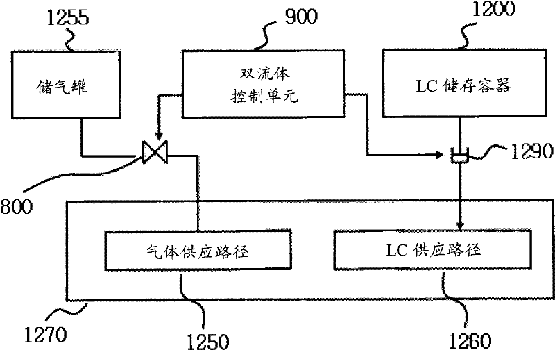
[0022] figure 2 is a block diagram showing a liquid crystal dispenser employing a method for dropping liquid crystals according to an embodiment of the present invention. like figure 2 As shown, the liquid crystal dispenser adopting the method for dripping liquid crystal according to the embodiment of the present invention includes a two-fluid control unit 900, a gas supply path 1250, a liquid crystal (LC) supply path 1260, a constant liquid crystal (LC) feeder 1290 and Gas regulating valve 800.

[0023] The ...


PUM


Abstract

The invention discloses a method used for liquid crystal dripping. In the method used for dripping liquid crystal to a substrate, liquid crystal is introduced into a liquid crystal supply path, and is made to drip through a nozzle via injecting gas to liquid crystal forming liquid crystal drops at a nozzle end part, the method comprises steps of: repetitively supplying a preset amount of liquid crystal to the liquid crystal supply path; and supplying gas required by the liquid crystal dripping from the nozzle end part, thereby making the liquid crystal drip.

Description

technical field [0001] The present invention generally relates to a liquid crystal dispenser, and more particularly to a method for dripping liquid crystals onto a substrate. Background technique [0002] Generally, a liquid crystal display (LCD) includes a lower substrate, an upper substrate, a sealant, and a liquid crystal layer. The lower substrate has drive devices, such as transistors, on the flat glass. The upper substrate has a color filter layer on the flat glass. A sealant is used to attach the upper and lower substrates to each other. A liquid crystal layer is filled between the upper substrate and the lower substrate. Such an LCD drives liquid crystal molecules in a liquid crystal layer through a driving device formed on a lower substrate, and controls the intensity of light passing through the liquid crystal layer by driving the liquid crystal molecules, thereby displaying information. [0003] According to an LCD manufacturing method, a driving device is for...

Claims


Application Information

Patent Timeline
Patent Type & Authority Applications(China)
IPC IPC(8): G02F1/1341
CPCG02F1/1341
Inventor 金埈煐金熙根
Owner TOP ENG CO LTD
Learn More