Data transmission method and device
A data transmission method and data transmission technology, which are applied in the field of data transmission methods and devices, can solve the problems of low data transmission efficiency, data transmission can not meet the business volume of up and down, and achieve the effect of improving data transmission efficiency
- Summary
- Abstract
- Description
- Claims
- Application Information
AI Technical Summary
Problems solved by technology
Method used
Image

Examples
Embodiment 1
[0047] This embodiment provides a data transmission method, and this embodiment combines the foregoing embodiments and preferred implementation manners therein.
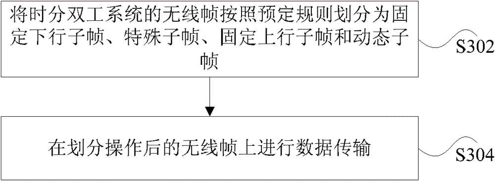
[0048] The method comprises the steps of:
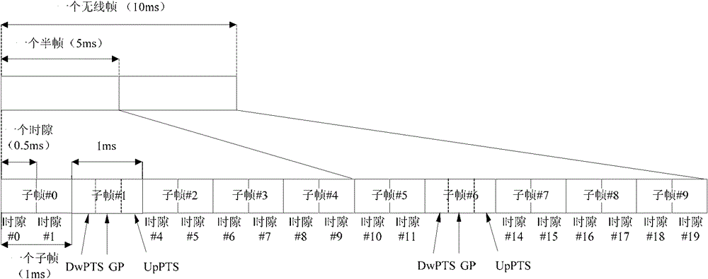
[0049] Step 1: Divide a wireless frame, and a divided wireless frame includes: fixed downlink subframes, special subframes, fixed uplink subframes, and dynamic subframes. Wherein, the special subframe includes DwPTS, GP, and UpPTS. The dynamic subframe transmits an uplink signal or a downlink signal or does not transmit any signal.
[0050] Step 2: The base station notifies one or more or all terminals in the cell on the fixed downlink subframe or dynamic subframe preceding the dynamic subframe that the dynamic subframe is used to transmit uplink signals or downlink signals or not transmit any signals. The notification can be explicit or implicit.
[0051] Preferably, the explicit way in step 2 is to notify through specific signaling. An implicit method is to judge whet...
Embodiment 2
[0058] This embodiment provides a data transmission method. This embodiment combines the above embodiments and preferred implementation modes. In this embodiment, the downlink grant and PDSCH are sent on the same dynamic subframe, and the ACK is sent on the fixed uplink subframe. / NACK.
[0059] Specifically, in this embodiment, in a wireless frame, subframes 0 and 5 are fixed downlink subframes; subframes 2 and 7 are fixed uplink subframes; subframes 1 and 6 are special subframes, including DwPTS, GT, UpPTS; subframes 3, 4, 8, and 9 are dynamic subframes.
[0060] Figure 4 It is a schematic diagram of the timing relationship of the data transmission method according to the embodiment of the present invention Figure 1 ,Such as Figure 4 As shown, the downlink grant and PDSCH are sent on the same dynamic subframe, and the ACK / NACK is sent on the fixed uplink subframe. For example: the base station sends downlink grant signaling in subframe 3 of radio frame A+1, sends PDSC...
Embodiment 3
[0062] This embodiment provides a data transmission method. This embodiment combines the above embodiments and preferred implementation modes. In this embodiment, an uplink grant is sent on a fixed downlink subframe or DwPTS, and a corresponding PUSCH is sent on a dynamic subframe. ACK / NACK is sent on fixed downlink subframes.
[0063] Specifically, in a radio frame in this embodiment, subframes 0 and 5 are fixed downlink subframes; subframes 2 and 7 are fixed uplink subframes; subframes 1 and 6 are special subframes, including DwPTS, GT , UpPTS; subframes 3, 4, 8, and 9 are dynamic subframes.
[0064] Figure 5 It is a schematic diagram of the timing relationship of the data transmission method according to the embodiment of the present invention Figure II ,Such as Figure 5 As shown, the uplink grant is sent on the fixed downlink subframe or DwPTS, the corresponding PUSCH is sent on the dynamic subframe, and the ACK / NACK is sent on the fixed downlink subframe. For examp...
PUM
 Abstract
Description
Claims
Application Information