Airplane wingtip device

A wingtip and aircraft technology, applied in the direction of wing shape, heat reduction structure, etc., can solve problems such as large bending moment, increased structural weight, and the influence of aircraft flutter characteristics, to reduce eddy current strength, reduce structural weight, and flutter Features with little effect

Active Publication Date: 2011-08-31
COMAC +1
View PDF5 Cites 3 Cited by
  • Summary
  • Abstract
  • Description
  • Claims
  • Application Information

AI Technical Summary

Problems solved by technology

[0008] Although the up-trans winglets and wingtip sails have obvious drag reduction effects, both the winglets and the wingtip sails have relatively large be

Method used


Image

  • Airplane wingtip device
  • Airplane wingtip device
  • Airplane wingtip device

Examples


Embodiment Construction

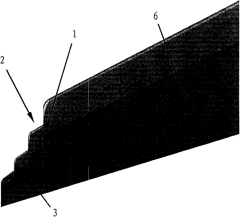
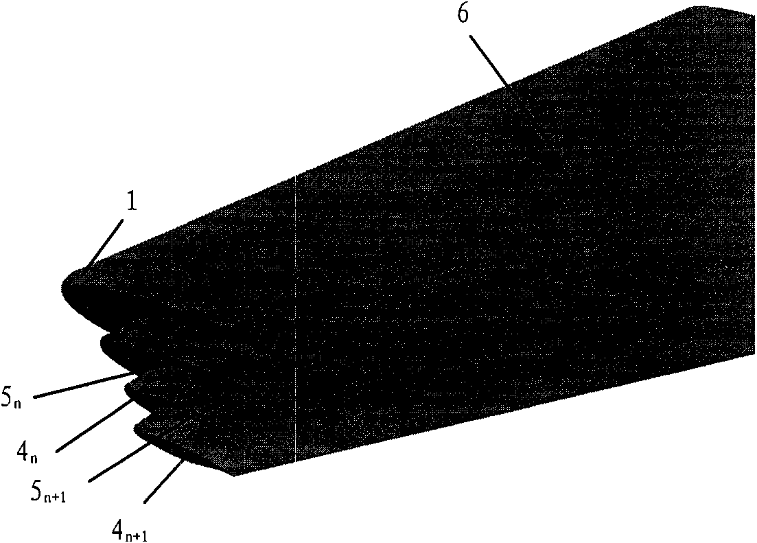
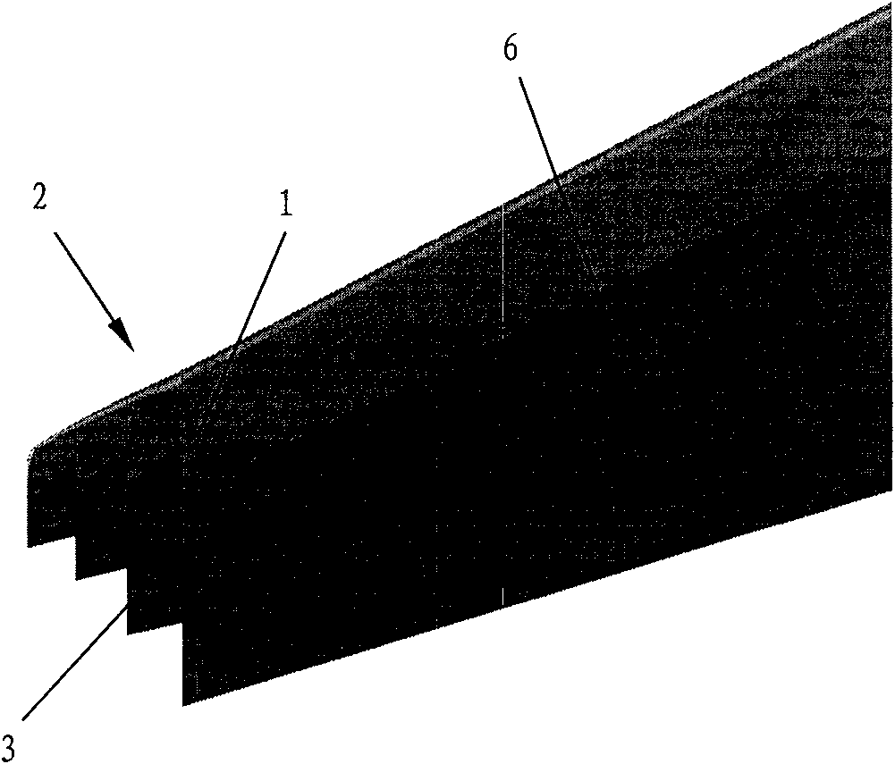
[0044] Such as figure 1 and figure 2 As shown, in one embodiment of the present invention, the aircraft wingtip device is in a multi-step shape, which includes a transition portion 1 and a wingtip portion 2, and the inner end of the transition portion 1 is connected to the far end of the aircraft wing 6 , the connection between the outer end of the transition portion 1 and the wing tip 2, wherein the wing tip includes a plurality of wing tip segments 3 n , each wingtip segment includes wingtip 4 n and wing root 5 n , the first wingtip segment 3 1 wing root 5 1 Connected to the outer end of the transition portion 1 and aligned with the trailing edge of the outer end of the transition portion 1, the n+1th wing tip segment 3 n+1 wing root 5 1 Located at the nth wingtip segment 3 n Wingtip 4 n on, and the n+1th wingtip segment 3 n+1 wing root 5 1 The chord length is less than the nth wingtip segment3 n Wingtip 4 n Chord length, where n>0. Additionally, if figure 1 A...


PUM


Abstract

The invention provides an airplane wingtip device which comprises a transition part and a wingtip part. The inner end part of the transition part is connected with the far end of an airplane wing, and the outer end part of the transition part is connected with the wingtip part; the wingtip part comprises a plurality of wingtip sections; and each wingtip section comprises a wingtip and a wing root respectively, the wing root of the first wingtip section is connected with the outer end part of the transition part, and arranged between the first edge and rear edge of the outer end part of the transition part, the wing root of the (n+1)th wingtip section is placed on the wingtip of the nth wingtip section, and the wing root chord length of the (n+1)th wingtip section is smaller than the wingtip chord length of the nth wingtip section, wherein n is larger than 0. The wingtip device provided by the invention is arranged in a step shape, so that more than one discontinuity surface is added on each wingtip of the wingtip device, wingtip vortexes induced by the wingtips are mutually inhibited, the vortex intensity is weakened, and the effect of reducing resistance is achieved. In addition, the wing root bending moment increment is smaller, the structural weight of an airplane is reduced, and the influence on the flutter characteristic is smaller as well.

Description

technical field [0001] The invention relates to a wingtip device of an aircraft wing. Background technique [0002] The lift required for the aircraft to maintain normal flight is generated by the pressure difference between the upper and lower surfaces of the wing. Due to the existence of the pressure difference between the upper and lower surfaces, the air on the lower surface of the wing near the wingtip will flow around to the upper surface, forming a wingtip vortex, causing the wing The pressure difference between the upper and lower surfaces of the wing in the area near the tip is reduced, resulting in a decrease in the lift generated in this area. [0003] In view of the above problems, winglets (winglets) are usually arranged on the wingtips of the aircraft wings. The main function of the winglets is to increase the effective aspect ratio without increasing the span length of the aircraft. In this way, the two-dimensional effect of the wing is enhanced, the induced ...

Claims


Application Information

Patent Timeline
IPC IPC(8): B64C3/10B64C3/36
Inventor 张淼陈迎春张美红刘铁军薛飞于哲慧汪君红马涂亮张冬云周峰
Owner COMAC
Why Eureka
Try Eureka