
Transmission roller mold

A technology for conveying rollers and moulds, which is applied in manufacturing tools, ceramic molding machines, etc., and can solve problems such as air bubbles, insufficient compaction, and air mixing

Inactive Publication Date: 2011-09-14
维苏威赛璐珂陶瓷(苏州)有限公司
View PDF6 Cites 0 Cited by
  • Summary
  • Abstract
  • Description
  • Claims
  • Application Information

AI Technical Summary

Problems solved by technology

[0002] The existing roll-making molds all use upper feeding, and the disadvantage of this is that the produced rolls are not fully compacted during the roll-making process or air is mixed in to generate air bubbles, which affects the roll's quality. quality

Method used


Image

  • Transmission roller mold
  • Transmission roller mold
  • Transmission roller mold

Examples


Embodiment Construction

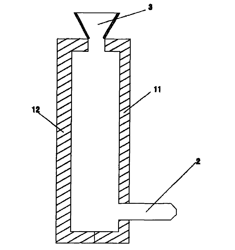
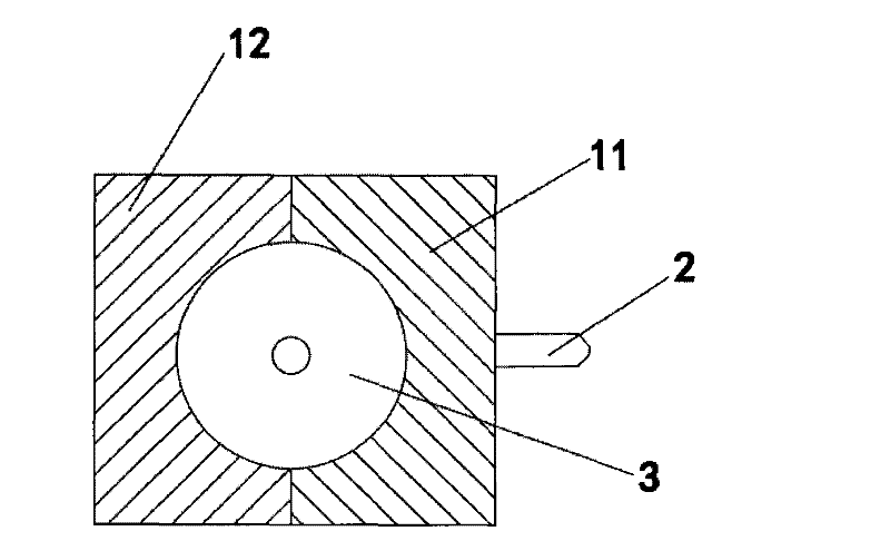
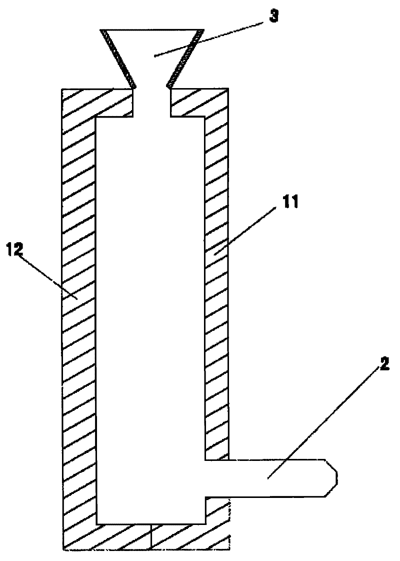
[0017] The present invention discloses a transfer roller mould, which comprises a first mold 11 and a second mold (12). The first mold 11 and the second mold 12 are closed and tightened by a tightening belt (not shown in the figure). After the mold, a cylindrical mold core with a circular opening at the upper end and a closed lower end is formed. A circular tube protrudes from the bottom of the first mold 11 to form an injection device 2 , and a funnel 3 is provided at the top of the mold. The lower end opening of the funnel 3 communicates with the circular opening behind the mold closing.

[0018] When the mold is in use, the first mold 11 and the second mold 12 are first tightened by a tightening belt, and the slurry is injected into the mold from the injection device 2 below the first mold 11 through a vacuum pump. When the slurry is full of the mold, it will cause the backflow of the material when it is left to form the mold. In order to prevent the backflow from causing t...


PUM


Abstract

The invention provides a transmission roller mold, which comprises a first mold and a second mold, wherein a cylindrical mold core is formed after the first mold is combined with the second mold; an injection device is arranged below the first mold; and a funnel is arranged on the top of the mold. The invention has the advantages that: liquid materials are conveyed by the mold from the lower side to the upper side, so that the materials are more compact, air is removed, and a manufactured transmission roller is firmer. The defect of incompleteness of the roller caused by backflow is overcome due to the arrangement of the funnel.

Description

technical field [0001] The invention relates to a mold, in particular to a mold suitable for making a transmission roller. Background technique [0002] The existing roll-making molds all use upper feeding, and the disadvantage of this is that the produced rolls are not fully compacted during the roll-making process or air is mixed in to generate air bubbles, which affects the roll's quality. quality. Contents of the invention [0003] The object of the present invention is to solve the above-mentioned technical problems, and to provide a conveying roller mould. [0004] The purpose of the present invention is achieved through the following technical solutions: [0005] A conveying roller mold, characterized in that: comprising a first mold and a second mold, the first mold and the second mold are molded together to form a cylindrical mold core, an injection device is arranged under the first mold, the A funnel is arranged on the top of the mold. [0006] Further, in t...

Claims


Application Information

Patent Timeline
Patent Type & Authority Applications(China)
IPC IPC(8): B28B7/00
Inventor 张习熠徐孝仁张惠林
Owner 维苏威赛璐珂陶瓷(苏州)有限公司
Learn More