
Design method for interference-free installation of gear tooth phase of internal gear ring plate in outer three-ring speed reducer

A design method and technology of internal gear ring, applied in the direction of gear transmission, belt/chain/gear, mechanical equipment, etc., can solve the problem of lack of three-phase internal gear ring plate and so on

Inactive Publication Date: 2011-09-14
TIANJIN UNIVERSITY OF TECHNOLOGY
View PDF6 Cites 1 Cited by
  • Summary
  • Abstract
  • Description
  • Claims
  • Application Information

AI Technical Summary

Problems solved by technology

[0029] The purpose of the present invention is to solve the problem that in the existing outer three-ring reducer technology, due to the lack of theoretical support for the phase relationship between the teeth of the three-phase inner ring plates, the teeth of the three inner ring plates often collide with the teeth of the outer gear. To solve the problem of interference, provide a non-interference installation method for the gear teeth of the inner ring plate of the outer three-ring reducer so that the teeth of the three inner ring plates in the outer three-ring reducer do not interfere with the teeth of the outer gear. design method

Method used


Image

  • Design method for interference-free installation of gear tooth phase of internal gear ring plate in outer three-ring speed reducer
  • Design method for interference-free installation of gear tooth phase of internal gear ring plate in outer three-ring speed reducer
  • Design method for interference-free installation of gear tooth phase of internal gear ring plate in outer three-ring speed reducer

Examples


Embodiment Construction

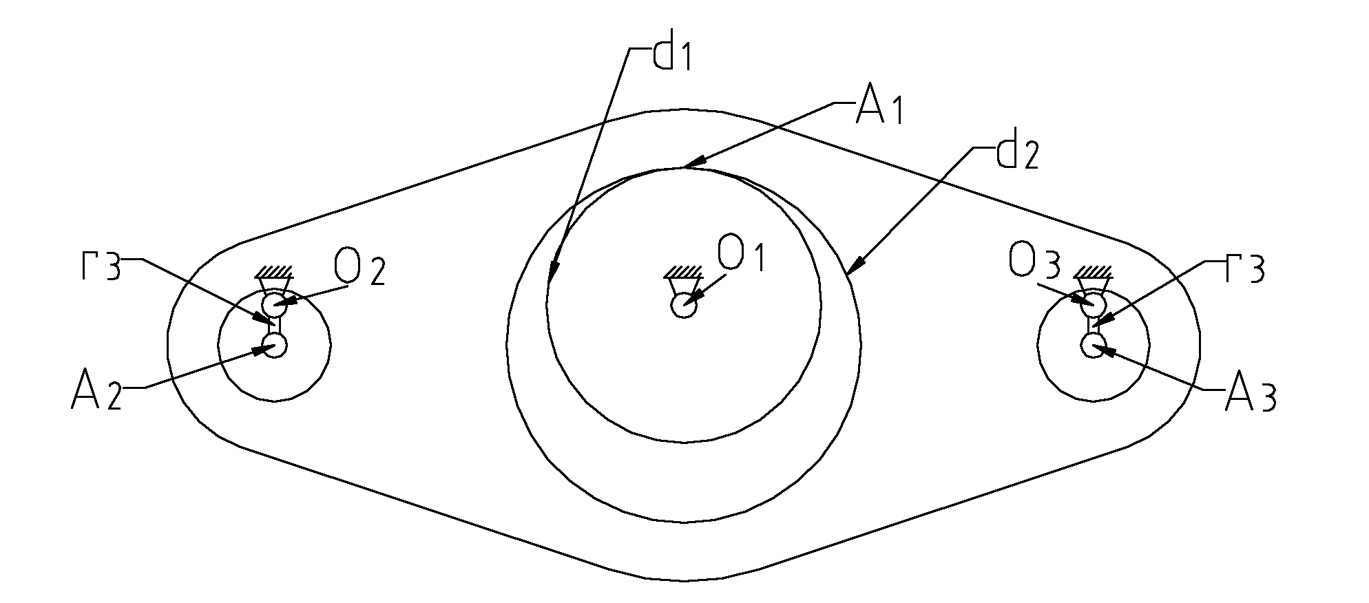
[0130] The present invention relates to the gear tooth phase technology for the non-interference assembly of the three-phase inner gear ring plate of the outer three-ring reducer. Before that, because there was no relevant theoretical support, whether it is in the design stage or in production, it can be said that it is related to this The solution to the problem is in a state of blindness. The method of the invention can effectively solve this problem.

[0131] The content of the design method for the non-interference installation of the tooth phase of the inner gear ring plate of the outer three-ring reducer provided by the present invention is as follows:

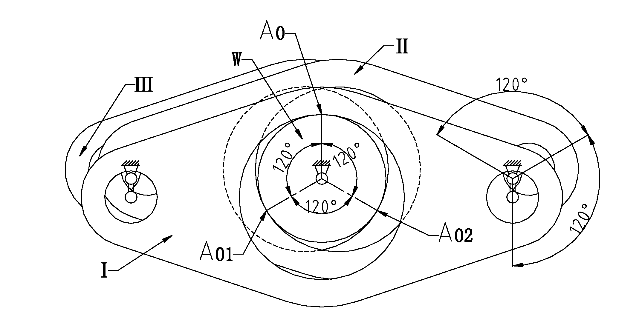
[0132] 1. Determination of the tooth phase angle of the inner gear ring plate of the outer three-ring reducer, also known as the spin angle

[0133] Based on the first (No. 0) inner gear ring plate, determine the phase angle Pn of the second (No. 1) and third (No. 2) inner gear ring plate teeth according to the followin...


PUM


Abstract

The invention discloses a design method for interference-free installation of a gear tooth phase of an internal gear ring plate in an outer three-ring speed reducer, comprising the steps of: determining a gear tooth phase angle of the internal gear ring plate of the outer three-ring speed reducer; determining an equivalent phase angle beta of the gear tooth of the internal gear ring plate of the outer three-ring speed reducer, wherein the equivalent phase angle beta is provided with a confirmable indexing; constructing a precise angle value table of the phase angle by calculating and screening out the precise angle value of the gear tooth phase angle of the internal gear ring plate according to a computational formula (7) for the equivalent phase angle beta of the gear tooth of the internal gear ring plate of the outer three-ring speed reducer, wherein the equivalent phase angle beta is provided with a confirmable indexing; and determining the relationship between the rotating direction and the positive and the negative numbers of values of the gear tooth phase angles of second and third internal gear ring plates. By use of the design method, a gear pair without the precise phase relationship is avoided becoming a product with an original defect in the design period, and the test assembly in the engineering is changed to be precise fit, therefore, the problems of the outer three-ring speed reducer, such as vibration, noise, tooth surface abrasion and low efficiency, are solved, the manufacture cost is reduced, the product performance is improved, and the three-ring speed reducer is popularized.

Description

【Technical field】: [0001] The invention belongs to the technical field of reducers, and in particular relates to a method and practical data for determining the phase angle of an inner gear of an outer three-ring reducer. 【Background technique】: [0002] At present, the reducers commonly used at home and abroad can be roughly divided into two categories in addition to worm gear and worm reducers: the first type is ordinary cylindrical gear reducers; the second type is planetary reducers, including cycloidal pin gear reducers device. The cylindrical gear reducer belongs to the parallel shaft transmission, its input shaft and output shaft are parallel to each other, and the axis is fixed. Its advantages are simple structure and convenient maintenance; its disadvantages are small transmission ratio, large relative mass and weak carrying capacity. The planetary reducer belongs to the coaxial driving shaft transmission, its input shaft and output shaft are on the same center li...

Claims


Application Information

Patent Timeline
Patent Type & Authority Applications(China)
IPC IPC(8): F16H1/32
Inventor 沈兆奎
Owner TIANJIN UNIVERSITY OF TECHNOLOGY
Learn More