
Operation wire harness connection device and endoscope

A technology of connecting device and endoscope, applied in the field of endoscope, can solve the problems of inability to adjust the spacing between teeth, inability to adjust, and inability to precisely adjust the loosening of operating wire harnesses, etc.

Inactive Publication Date: 2011-09-21
FUJIFILM CORP
View PDF10 Cites 10 Cited by
  • Summary
  • Abstract
  • Description
  • Claims
  • Application Information

AI Technical Summary

Problems solved by technology

[0007] However, in the device described in Japanese Patent Application Laid-Open No. 4-6724, when adjusting the slack of the operating harness, when the adjustment exceeds the range in which the threaded sleeve and the nut member are screwed together, the operating harness must be fixed. and the threaded sleeve's solder melts for reinstallation, which is time-consuming and labor-intensive
[0008] In the connection devices described in Japanese Patent Application Publication No. 2000-51146, Japanese Patent Application Publication No. 2000-51148, and Japanese Patent Application Publication No. 2008-92968, although the position of the circular groove in which the engaging member engages can be changed, the Multi-stage adjustments are possible, but adjustments below the pitch between the circular grooves are not possible, making it impossible to finely adjust the slack in the operating harness
Furthermore, the connecting member of Japanese Patent Laid-Open No. 2006-6760 cannot be adjusted below the pitch of the teeth formed on the rack.

Method used


Image

  • Operation wire harness connection device and endoscope
  • Operation wire harness connection device and endoscope
  • Operation wire harness connection device and endoscope

Examples


Embodiment Construction

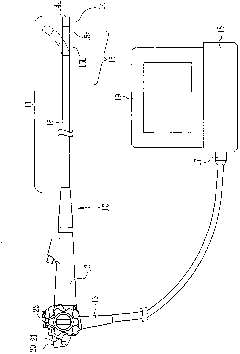
[0034] exist figure 1 Among them, an endoscope 10 includes an elongated insertion portion 11, an operation portion 12 provided on the proximal end side of the insertion portion 11, a universal cord 13, and the like. The insertion part 11 is formed in a tubular shape and includes a front end part 14 , a curved part 15 , and a flexible part 16 in this order from the front end. The bending portion 15 includes a first bending portion 15a that is bent in the vertical direction and a second bending portion 15b that is bent in the left-right direction. One end of the universal cord 13 is connected to the operation unit 12 , and the connector unit 17 at the other end is connected to the processor unit 18 , air supply unit (not shown), light source unit (not shown), and the like.

[0035] The front end portion 14 has a cap shape formed of a hard resin material. As is well known, the front end surface 14a of the front end portion 14 is provided with an illumination window for irradiat...


PUM


Abstract

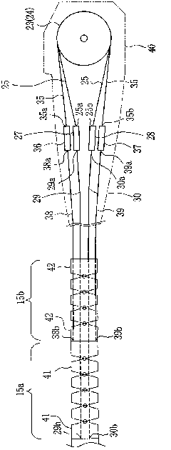
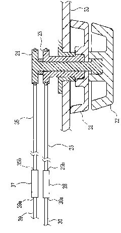
The present invention provides an operation wire harness connection device and an endoscope. The endoscope is provided with an operation part and an insertion part. The insertion part is provided with the following components: a front part which has an observation function; a bending part which is used for causing direction change of the front part; and a flexible part which has flexibility. When an operation handle on an operation part is rotated, a traction driving wire harness moves. The traction driving wire harness is connected with an operation wire harness which is used for bending the bending part. The connection device is provided with the following components: an external thread component which fixes the operation wire harness; a snapping component which is provided with internal threads that are screwed with the external thread component; and a keeping mechanism which can change the filling position of the snapping component through a step mode. Fine adjustment for the slack of the operation wire harness is performed through changing screwing-into amount of the external thread component, wherein coarse adjustment for the slack of the operation wire harness is performed through changing the filling position of the snapping component through a step mode.

Description

technical field [0001] The present invention relates to an operating wire harness coupling device and an endoscope using the same. Background technique [0002] The endoscope includes an insertion portion inserted into a body cavity, and an operation portion provided on a proximal end side of the insertion portion. The insertion part includes a front end part, a bending part and a flexible part. The front end portion is formed in a cap shape from a hard resin material, and an objective lens, a solid-state imaging element such as a CCD, an illumination lens, and the like are arranged therein. By advancing and retreating the operation wire harness in the insertion part, the bending part can be bent up and down or left and right, so that the insertion part can be smoothly inserted into the body cavity, or the distal end can be oriented in a desired direction in the body. The flexible part is a long flexible pipe part and is located between the operation part and the bending p...

Claims


Application Information

Patent Timeline
IPC IPC(8): A61B1/005A61B1/008
Inventor 三芳由希子
Owner FUJIFILM CORP
Learn More