

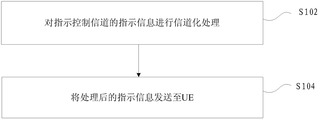
Method and device for indicating control channel
A control channel and control channel area technology, applied in the field of indicating control channels, can solve the problems that the accuracy of new resource control information transmission cannot be guaranteed, and the transmission mode of control information on new resources has not been determined.
- Summary
- Abstract
- Description
- Claims
- Application Information
AI Technical Summary
Problems solved by technology
Method used
Image

Examples
Embodiment 1
[0074] Embodiment 1: In this embodiment, the indication information only includes the time domain position information of the control channel area
example 1
[0075] Example 1. The control channel area is on the first time slot:
[0076] method 1,
[0077] The control channel region is K consecutive OFDM symbols starting from the Sth OFDM symbol in the first time slot;
[0078] Application 1, S, K are given by the instruction information;
[0079] Application 2, S is predefined, and K is given by the instruction information;
[0080] Application 3, S is given by the instruction information, and K is predefined.
[0081] Method 2,
[0082] The control channel area is K consecutive OFDM symbols starting from the first OFDM symbol in the first time slot; K is given by the indication information.
[0083] Example 2. The control channel area is on the second time slot:
[0084] method 1,
[0085] The control channel region is K consecutive OFDM symbols starting from the Sth OFDM symbol in the second time slot;
[0086] Application 1, S, K are given by the instruction information;
[0087] Application 2, S is predefined, and K is ...
Embodiment 2
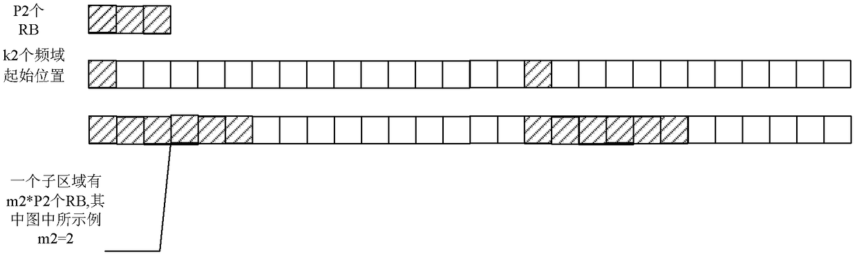
[0093] Embodiment 2: In this embodiment, the indication information only includes the frequency domain position information of the control channel region
[0094] Example 1. The frequency domain area is the sum (union) of k2 such sub-areas. Any one of the sub-areas here is: m2*P2 resource blocks RB consecutively in ascending order from a predetermined starting position; where P2 is the predetermined , k2 starting positions are predefined, and m2 is given by the instruction information. Its schematic diagram is as follows figure 2 shown.
PUM
 Abstract
Description
Claims
Application Information