

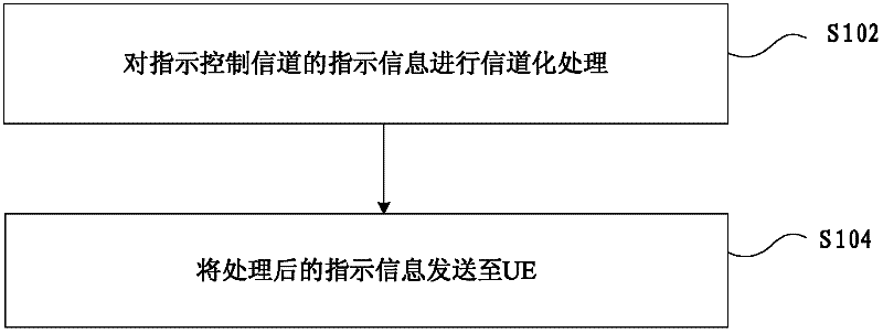
Method and device for indicating control channel
A technology of control channel and control channel area, applied in the field of indication control channel, can solve the problems of not being able to guarantee the accuracy of the transmission of control information on new resources, and the transmission mode of control information on new resources is not determined.
- Summary
- Abstract
- Description
- Claims
- Application Information
AI Technical Summary
Problems solved by technology
Method used
Image

Examples
Embodiment 1
[0074] Embodiment 1: In this embodiment, the indication information only includes the time domain position information of the control channel area
[0075] Example 1. The control channel area is on the first time slot:
[0076] method 1,
[0077] The control channel region is K consecutive OFDM symbols starting from the Sth OFDM symbol in the first time slot;
[0078] Application 1, S, K are given by the instruction information;
[0079] Application 2, S is predefined, and K is given by the instruction information;
[0080] Application 3, S is given by the instruction information, and K is predefined.
[0081] Method 2,
[0082] The control channel area is K consecutive OFDM symbols starting from the first OFDM symbol in the first time slot; K is given by the indication information.
[0083] Example 2. The control channel area is on the second time slot:
[0084] method 1,
[0085] The control channel region is K consecutive OFDM symbols starting from the Sth OFDM symbo...
Embodiment 2
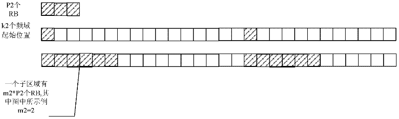
[0093] Embodiment 2: In this embodiment, the indication information only includes the frequency domain position information of the control channel region
[0094] Example 1. The frequency domain area is the sum (union) of k2 such sub-areas. Any one of the sub-areas here is: m2*P2 resource blocks RB consecutively in ascending order from a predetermined starting position; where P2 is the predetermined , k2 starting positions are predefined, and m2 is given by the instruction information. Its schematic diagram is as follows figure 2 shown.
[0095] Example 2. The method mentioned in typ0 / 1 / 2 used in resource allocation (Resource allocation) in document 3GPP TS 36.213 is adopted.
Embodiment 3
[0096] Embodiment 3: In this embodiment, the indication information includes the frequency domain position information of the control channel area + the method of indicating the control channel area
[0097] The indication information provides an indication of the position in the frequency domain, and at the same time provides a method for indicating the position in the frequency domain.
[0098] For specific applications, the base station is configured with multiple methods for indicating the frequency domain position, and the UE needs to use the correct method to understand the indication of the frequency domain position given by the base station, so as to obtain information about the frequency domain position.
[0099] Furthermore, for the method of indicating the control channel area, use the combination of bit 0 and 1 to clearly tell the UE the method of indicating the control area currently used, such as Table 4:
[0100] Table four
[0101]
PUM
 Abstract
Description
Claims
Application Information